Download
1 / 44
460 likes | 491 Views
Embedded Computing Chapter 1. COE 306: Introduction to Embedded Systems Dr. Aiman El-Maleh Computer Engineering Department College of Computer Sciences and Engineering King Fahd University of Petroleum and Minerals. Next. What are Embedded Computing Systems ?

E N D
Embedded ComputingChapter 1 COE 306: Introduction to Embedded Systems Dr. Aiman El-Maleh Computer Engineering Department College of Computer Sciences and Engineering King Fahd University of Petroleum and Minerals
Next . . . • What are Embedded Computing Systems? • Challenges in Embedded Computing System Design • Design Methodology • Formal System Description: UML
What is an Embedded System? • Embedded computing system: any device that includes a programmable computer but is not itself a general-purpose computer. • Take advantage of application characteristics to optimize the design: • don’t need all the general-purpose bells and whistles. • Examples: calculator, fax, clock, coffee maker, cell phone, printer, TV, microwave, camera, car (40–100 microcontrollers) • It all started from a calculator: using Intel 4004 microprocessor
Embedding a Computer • Microcontroller: includes CPU, I/O devices, on-board memory.
Application Examples • Simple control: front panel of microwave oven, etc. • Canon EOS 3 has three microprocessors. • 32-bit RISC CPU runs autofocus and eye control systems. • Digital TV: programmable CPUs + hardwired logic. • Today’s high-end automobile may have 100 microprocessors: • 4-bit microcontroller checks seat belt; • microcontrollers run dashboard devices; • 16/32-bit microprocessor controls engine: determining when spark plugs fire, controlling the fuel/air mixture, etc. • Low-end cars use 20+ microprocessors.
BMW 850i Antilock Brake System • An antilock brake system (ABS) reduces skidding by pumping the brakes. • The purpose of an ABS is to temporarily release the brake on a wheel when it rotates too slowly.
Cyber-Physical Systems • A physical system that tightly interacts with a computer system. • The embedded computer is the cyber-part of the cyber-physical system. • Computers replace mechanical controllers: • More accurate. • More sophisticated control. • Engine controllers replace distributor, carburetor, etc. • Complex algorithms allow both greater fuel efficiency and lower emissions.
Characteristics of Embedded Systems • Sophisticated functionality • Often have to run sophisticated algorithms or multiple algorithms: e.g., a microprocessor controlling automobile engine • Often provide sophisticated user interfaces: e.g. moving maps in Global Positioning System (GPS) • Real-time operation • Must finish operations by deadlines. • Hard real time: missing deadline causes failure; e.g., missed deadlines in printers can result in scrambled pages • Soft real time: missing deadline results in degraded performance; e.g., Streaming audio-video • Many systems are multi-rate: must handle operations at widely varying rates; audio and video of a multimedia stream run at very different rates, but they must remain closely synchronized.
Characteristics of Embedded Systems • Low manufacturing cost • Many embedded systems are mass-market items that must have low manufacturing costs. Cost is determined by type of microprocessor, amount of memory, type of I/O devices. • Low power • Power consumption is critical in battery-powered devices. • Excessive power consumption increases system cost even in wall-powered devices. • Designed to tight deadlines by small teams • Often designed by a small team of designers. • Often must meet tight deadlines: 6 month market window is common; Can’t miss back-to-school window for calculator.
Implementation Alternatives • Microprocessor, custom hardware (ASICs), FPGAs
Why Use Microprocessors? • Efficient • 1+ IPC for modern RISC processors • Large design teams / mass production • Highly optimized (speed, power) • Latest manufacturing technology (fabrication) • Single-design for multiple functions / general-purpose • Implementing several functions on a single processor often makes much better use of the available hardware budget • Flexible • Separate hardware/software design by different teams • Easier to design cost-effective families/generations of products
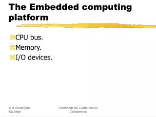
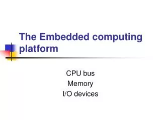
Embedded Computing Platform • Embedded computing platform: hardware architecture + associated software. • Why not use PCs for all embedded computing? • real-time performance requirements often drive us to different architectures • low power and low cost also drive us away from PC architectures and toward multiprocessors • Custom embedded systems that are designed for an application, such as a cell phone • burn several orders of magnitude less power than do PCs with equivalent computational performance, • they are considerably less expensive as well.
Challenges in Embedded System Design • How much hardware do we need? • type of microprocessor, amount of memory, peripheral devices— performance-cost tradeoff • How do we meet deadlines? • Faster hardware or cleverer software? • Faster hardware increases cost and power consumption • How do we minimize power? • Turn off unnecessary logic? Reduce memory accesses? • Careful design is required to slow down noncritical parts of the machine while still meeting necessary performance goals • Excessive power consumption reduces battery life and increases heat dissipation
Challenges in Embedded System Design • How do we design for upgradeability? • Support multiple versions/generations using the same hardware • How can we design a machine that will provide the required performance for software that we haven’t yet written? • Does it really work? • Is the specification correct? • Does the implementation meet the spec? • How do we test for real-time characteristics? • How do we test on real data? • How do we work on the system? • Limited observability and controllability; no keyboard and screen • Restricted development environments
Performance of Embedded Computing Systems • In general-purpose computing, performance often means average-case, may not be well-defined. • In real-time systems, performance means meeting deadlines: Missing the deadline by even a little is bad. • We need to analyze the system at several levels of abstraction to understand performance: • CPU: pipelined CPU with a cache • Platform: bus and I/O devices • Program: structure and overall behavior • Task: multitasking system with tasks interaction • Multiprocessor: interaction between processors
The Computing Stack EE 202, EE 203
Importance of Design Methodology • Design methodology is a procedure for designing a system. • Helps in tracking design objectives and keeps a scorecard on design to ensure nothing is skipped. • Compilers, software engineering tools, computer-aided design (CAD) tools, etc., can be used to: • help automate methodology steps; • keep track of the methodology itself. • Team communication and coordination • a design methodology makes it much easier for members of a design team to communicate.
Design Goals • Functionality and user interface • Performance • Overall speed, deadlines • Manufacturing cost • Power consumption • Other requirements (physical size, weight, etc.)
Embedded System Design Process • Top-down design: • start from most abstract description; • work to most detailed. • Bottom-up design: • work from small components to big system. • Real design uses both techniques. • At each level of abstraction, we must: • analyze the design to determine how to meet specifications; • refine the design to add detail. Requirements Specification Architecture Component Design System Integration
Requirements • Plain language description of what the user wants and expects to get. • Functional requirements • output as a function of input. • Non-functional requirements • Performance: time required to compute output; • Cost: includes manufacturing and nonrecurring engineering (NRE) costs • Physical size and weight • power consumption, reliability; etc. • Validating requirements: mock-ups, physical non-functional models.
Requirements Analysis • Requirements analysis • Check for requirements consistency; • Requirements form (summary) Types of data: Analog? Digital? Data Characteristics: Periodically arriving data? Occasional user inputs? #bits per data element? Types of I/O devices: Buttons? Analog/Digital Conv.? Video displays?
Example: GPS Moving Map Requirements • Moving map obtains position from GPS, paints map from local database. • Functionality: For automotive use. Show major roads and landmarks. • Userinterface: At least 400 x 600 pixel screen. Three buttons max. Pop-up menu. • Performance: Map should scroll smoothly. No more than 1 sec power-up. Lock onto GPS within 15 seconds. • Cost: $120 street price = approx. $40 cost of goods sold. • Physical size/weight: Should fit in hand. • Power consumption: Should run for 8 hours on four AA batteries.
Specification • A formal more precise description of the system that reflects the customer’s requirements in a way that can be clearly followed during design. • should not imply a particular architecture; • provides input to the architecture design process. • A contract between the customer and the architects • Clarifies design objectives and prevents faulty assumptions • Should be: • Understandable: so it can be verified against requirements • Unambiguous: so designers are clear about what to build
GPS Specification • Should include: • data received from the GPS satellite constellation; • map data; • user interface; • operations required to satisfy user requests; • background operations needed to keep the system running. • Unified Modeling Language (UML) is a language used for describing specifications.
Architecture Design • Purpose of architecture is to describe how the system implements required functions • Plan for overall structure of the system • What major components are needed for satisfying the specification? • Hardware components: CPUs, peripherals, etc. • Software components: major programs and their operations. • Block diagrams: General architecture, Hardware architecture, Software architecture • Must satisfy functional and non-functional requirements
GPS Moving Map Block Diagram • Shows major operations and data flows among them display GPS receiver search engine renderer database user interface General Architecture
GPS Moving Map Hardware Architecture display frame buffer CPU GPS receiver memory panel I/O
GPS Moving Map Software Architecture • Timer used to control when we read the buttons on the user interface and render data onto the screen database search renderer pixels position user interface timer
Designing Hardware and Software Components • Building system components in conformance to the architecture and specification. • Some components are ready-made, some are modified from existing designs, others designed from scratch. • Ready-made, standard components • CPU, memory, GPS receiver • Software library, topographic data databases • Custom components • PCB, FPGA • Custom software modules
System Integration • Putting the system components together • Many bugs appear only at this stage • Have a plan for integrating components to uncover bugs quickly, test as much functionality as early as possible • Bug discovery • Building the system in phases • Testing • Inserting appropriate debugging facilities during design can help ease system integration problems. • Debugging facilities for embedded systems are usually much more limited than what you would find on desktop systems; always a challenge.
Formal System Description • Unified Modeling Language (UML): A visual, object-oriented modeling language used to capture design tasks • Designed to be useful at many levels of abstraction in the design process • described as a number of interacting objects • some of those objects correspond to real pieces of software or hardware in system; others correspond to people or machines • Structural Description: the system components • Behavioral Description: how the system components act
Structural Description • Classes, interfaces, and objects • A class is a form of type definition. It defines attributesthat an object may have and operationsthat determine how the object interacts with the rest of the world.
The Class Interface • The operations provide the abstract interface between the class’s implementation and other classes. • Operations may have arguments, return values. • An operation can examine and/or modify object’s state. • Choose your interface properly • If the interface is too small/specialized: • object is hard to use and reuse. • If the interface is too large: • class becomes too cumbersome for designers to understand; • implementation may be too slow; spec and implementation are probably buggy.
Structural Description • A conceptual model, not tied to implementation • Relationships between classes: • Association: classes communicate but one does not own other. One class uses the functionalities provided by another class. • Aggregation: a complex class is made of several smaller classes. The child can exist independently of the parent. • Composition: aggregation in which owner does not allow access to its components. The child cannot exist independent of the parent. • Generalization: define one class in terms of another. Asuperclass has the most general attributes, operations, and relationships that may be shared with subclasses. A subclass may have more specialized attributes and operations.
Relations Examples Association Composition Aggregation
Class Derivation: UML Generalization • May want to define one class in terms of another. • Derived class inherits attributes, operations of base class
Links and Associations • Link: describes relationships between objects. • Association: describes relationship between classes. Links between objects Association between classes
Behavioral Description: State Machine • Event-driven: An event is some type of action. • It may originate outside the system or inside it. • Types of events • A signal is an asynchronous occurrence. It is defined in UML by an object that is labeled as a «signal». • A call event follows the model of a procedure call in a programming language. • A time-out event causes machine to leave state after certain amount of time.
Behavioral Description: Sequence Diagram • Shows sequence of operations over time • Describes how—and in what order—a group of objects work together • Shows a particular scenario
Summary • Embedded computers are all around us • Many systems have complex embedded hardware and software. • Embedded systems pose many design challenges: design time, deadlines, power, etc. • Design methodologies help us manage the design process. • Object-oriented design helps us organize a design. • UML is a transportable system design language • Provides structural and behavioral description primitives.