Download
1 / 29
290 likes | 293 Views
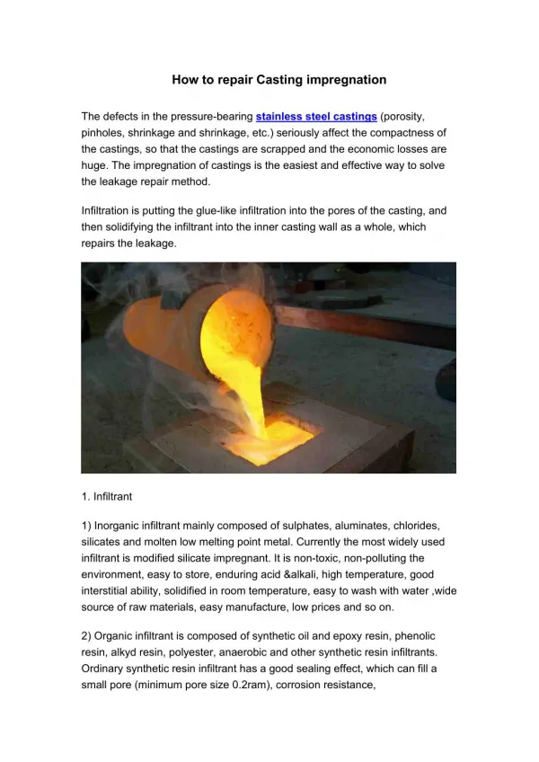
How to Repair ITM. Content. 1 Component 2 repair instruction 3 How to define problem 4 How to repair 5 How to disassemble 6 PC part 7 Button and Ports. 1.1Component. LED driver board. Power board. 60HZLEDscreen. PC power on button and touch pinboard. 182VG2.0 mother board. PC.

E N D
Content • 1 Component • 2 repair instruction • 3 How to define problem • 4 How to repair • 5 How to disassemble • 6 PC part • 7 Button and Ports
1.1\Component LEDdriver board Power board 60HZLEDscreen PCpower on button and touch pinboard 182VG2.0mother board PC touch screen external connection pinboard
1.2\ 6M48V2.0 Port Power port Audio port Back light port LVDS port Button port Remote control port USB HDMI1 HDMI2 VGA Audio input
1.3\182VG2.0 Port LVDSport Power port Button port Back light control Audio output Remote control port USB HDMI x 3 VGA 音频输入
2 repair instruction • Precaution • Make sure panel is shut down and power is cut. • Non-professional can not do repair • This manual is suit to panel model (black) • Tools • Screwdriver • Multimeter • PC/laptop • tweezers
2 repair instruction • Part can be replaced • TV • TV power board • TV mother board • Speakers • LVDS cable • Cables • Button board • Remote control receiver board • Touch screen pinboard • LED driver board • Touch screen • PC • Memory card • Hard disk • Mother board • CPU • Fan • PC power • Cables • Touch/button pinboard
3/How to define problem • Problem1:panelcan not power on • Check if power indicator is RED after power connects and power button is on. • When indicator is RED, use remote control to power on panel, if can power on, the power on/off button is fault. If remote control can not power on panel, to update TV mother board software. If update fail, to replace TV mother board. • When power indicator is not light • take off back cover of panel • Check electric of power switch button and power board, use multimeter to test if power output is good under 5V/12V/24V. • If there is no power, replace power board and check if panel works • When power indicator is not light and there is power from power board. • to check the connection between power board and TV mother board • to check TV mother board power port, if there is power • If there is power from TV mother board power port, to replace TV mother board
3/How to define problem Connect power and check power indicator is light Replace power switch or power board Check connections between power board and TV mother board Indicator is RED or Blue, but screen can not light on Replace TV mother board Update TV mother board by software Power on? Test Contact with supplier Power on? End
3/How to define problem • Problem2: Screen Blurred • Adjust TV software specs in factory mode (10 BIT or TIB) • If fail, to update TV mother board software • If not work, disassemble panel and check LVDS cable connection. • If LVDS cable connects good, to replace TV mother board • If screen still blurred after above steps, check if the screen is 120HZ. • If so, replace pinboard of 120HZ screen or update software.
3/How to define problem Adjust software specs Update TV mother board software Replace TV mother board Display ok Check LVDS connection or replace replace pin board of 120HZ screen or update software test Display ok end Contact supplier
3/How to define problem • Problem3: No signal • Check PC power indicator is YELLOW • If so, check resource setting is correct • If still no signal, check cable between PC and TV • Connect with external PC, if there is signal, PC has problem • When PC connects with TV by HDMI, replace it by VGA (to judge if port is wrong or connection not good) • If still no signal, take out the PC box and check memory card loose or dusty. • Replace memory card and check, if fail, replace PC mother board.
3/How to define problem PC power indicator is YELLOW Check power connection Check PC if fan works Replace PC power Connect with other PC, no signal Set signal resource Replace memory card or clean it Signal ok Replace TV mother board signal port Replace PC mother board test Signal ok Replace CPU end Check PC button and flat cable
3/How to define problem • Problem 4: screen can not display • When power on, after LOGO shows screen can not display • TV program damages, to update TV board. If not work, replace TV board • If still not display, take off panel cover and check back light cable connection • Screen can not display when power on • check power indicator is light • If power indicator do not light, it is problem 1
3/How to define problem Check connection of back light cable Organize back light cable and LVDS Screen can not display Update TV software Replace TV board Display is ok Display is ok test end Contact supplier
3/How to define problem • Problem 5:NO sound • Check if there is audio output from PC • If there is audio output from PC, check connection between PC and TV • If connection good, take off back cover of panel, test speaker by multimeter and check connections. Replace speaker when it is faulty. • If still on sound after above steps. To replace TV mother board or replace amplifier IC(TDA7491LP) on TV mother board.
3/How to define problem Check audio output from PC Check sound driver Check sound setting Check connections Check speakers Replace PC mother board Replace TV mother board Replace speakers Check sound Check audio output test end
4/Touch part repair 1. Touch part structure flat cable These PCB marked different number, there are different numbers on different size panel Black PCB is receiver, white PCB is sender. MCU is sender No.1. the position must be correct when repair Flat cable Flat cable PCB with USB cable
4/Touch part repair 2. How to define problem • Problem 1:can not touch • Connect panel with external PC, test by Checktool • If Checktool can not work, take off back cover and check USB port connection. If connection is good, take off touch screen and check touch port. Firstly, to see USB touch cable welding is good or not. • When welding is good, replace a good MCU and test. • If still not work after MCU replaced, to check PCB one by one.
4/Touch part repair Check connection between Pinboard and PC Connect panel with external PC Replace USB port on PC board Check flat cable, USB cable welding is good Replace cable or pinboard Replace MCU Check PCB one by one Touch is good Replace faulty PCB Touch is good end Contact supplier
4/Touch part repair • Problem 2: Touch is not smooth • Connect panel with external PC, check infrared part by Checktool. ( see picture next page) • For example, if tube 1-14 on No.2 PCB is faulty in picture next page • Find No.2 PCB from receiver or sender by multimeter, and then replace. • Or directly replace No. 2 PCB from receiver or sender, and check AD by checktool.
4/Touch part repair Fault is No.2 PCB Infrared tube number AD is 0, wrong number, so it is red Wrong AD
4/Touch part repair Checktool interface in English
5/How to disassemble • Take off all external connection cables and wall mount bracket • Take off back cover to check board, connections • If there is problem from touch part • Disconnect USB cable, button flat cable, control flat cable,etc • Take out fix part around four sides, see picture next pages • Take screen and glass to avoid dust • Replace touch part
5/How to disassemble The part fix screen and glass
5/How to disassemble Take out the screws Take out all screws around frame and take off screen and glass , put them together carefully to safe place
5/How to disassemble Touch frame Connect this part with PC, use Checktool to test and replace PCB
6/PCpart Touch button connect board Hard disk memory fan PCpower PCmother board
7/Button and Ports Audio input Power switch USB Touch 1.PC power on 4.menu 2.TVpower on 3. source HDMIport VGAport Volume adjust Channel adjust TVpower light PCpower light Power on, Light is red, light is blue when press TV button later Light is yellow when press PC button