Download

1 / 26
350 likes | 828 Views
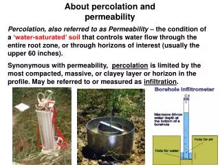
Permeability and seepage. Ms. Trupti Kshirsgar Assistant Professor Dept. of Civil Engineering. INDEX. Factors affecting permeability of soils Darcy’s law Determine of coefficient of permeability (1) laboratory method (2) filed method

E N D
Permeability and seepage Ms. Trupti Kshirsgar Assistant Professor Dept. of Civil Engineering
INDEX • Factors affecting permeability of soils • Darcy’s law • Determine of coefficient of permeability (1) laboratory method (2) filed method (3) indirect method • Application of flow net
Factors affecting permeability of soils • Particle size. • Properties of pore fluid. • Void ratio of soil. • Shape of particles. • Structure of soil mass. • Degree of saturation. • Adsorbed water. • Impurities in water.
1)Particle size :- permeability varies approximately as the square of grain size K=C*(D10)² k=coefficient of permeability(cm/sec) D10=effective diameter(cm) C= constant = between 100 and 150
2)Properties of pore fluid : The permeability is directly proportional to the unit weight of water and inversely proportional to is viscosity. K1/K2=n2/n1 It is usual practice to report the coefficient of permeability at 27°C. 3)Void ratio of soil : The coefficient of Permeability varies as e³/(1+e). For a given soil , greater the void ratio , the higher is the value of the coefficient of permeability.
4)Shape of particles : The permeability of soil depends upon the shape of particles. 5)Structure of soil mass : stratified soil deposits have greater permeability parallel to the plane of stratification then that perpendicular to this plane. 6) degree of saturation : If the soil is not fully saturated, it contains air pockets formed due to entrapped air. The presence of air in soils, causes blockage of passage and permeability is reduced.
7) Adsorbed water : the fine grained soils have a layer of adsorbed water strongly attaced to their surface. 8) Impurities in water : Any foreign matter in water has a tendency to plug the flow passage and reduce the permeability of soils.
DARCY’S LAW • The law of flow of water through soil was first studied by darcy in 1856. • “for laminar flow through saturated soil mass, the discharge per unit time is proportional to the hydraulic gradient. q=k* I *A q/A = k*I v = k* I
q = discharge per unit time A = total c/s area of soil mass. I = hydraulic gradient = h/L k = darcy’s coefficient of permeability • I = h/L = (h1 – h2)/L • q = k* (h1-h2)*A/L
DETERMINATION OF COFFICIENT OF PERMEABILITY 1) Laboratory methods A-: constant head permeability test B-: falling head permeability test 2) Field methods A-: pumping out tests B-: pumping in tests 3) Indirect methods A-: computation from the particle size B-: computation from consolidation test.
A) CONSTANT HEAD PERMEABILITY TEST Object : To determine the coefficient of permeability of a soil specimen by constant head methods.
Equipments : • Permeability mould, internal diameter = 100mm, effective height =127.3, capacity = 1000 ml, complete with all accessories. • Constant head tank. • Graduated cylinder, stop water, thermo meter. • Filter paper, vacuum pump. • Weighing balance, 0.1 gm accuracy.
B) FALLING HEAD PERMEABILITY TEST • Object : To determine the coefficient of permeability of a soil specimen by falling head method. • Equipment : All the equipment required for the constant head permeability test.
k= 2*3 a*l / A*t log10 h1/h2 Where, a= c/s area of stand pipe (cm2) • A= c/s area of soil sample • L= length of soil sample (cm) • t= time interval to fall head from h1 to h2 • h1= initial head (cm) • h2= final head (cm)
2. Field permeability tests 1) Pumping-out tests:- A-: for unconfined aquifer B-: for confined aquifer 2) Pumping –in tests:- A-: open end tests B-: single packer tests C-: double packer tests
1) Pumping-out Tests • For large engineering projects, it is the usual practice to measure the permeability of soils by pumping out tests. • This method is very useful for a homogeneous coarse • Grained soils which it is difficult to obtain undisturbed Sample. • The pumping out tests are very costly.
Aquifer • Aquiclude • Aquitard • Aquifuge • Unconfined aquifer • Confined aquifer
Pumping for confined aquifer • A confined flow condition occurs when the aquifer is confined both above and below by impermeable strate. Here, the draw down surface is , for all values of r , above the upper surface of the aquifer. • Consider the flow after steady state is reached .
2) Pumping –in tests • Pumping in tests are conducted to determine the coefficient of permeability of an individual stratum thorough which a hole is drilled.
The tests are more economical than pumping out tests • The water pumped is should be clean as impurities such as silt, clay or any other foreign matter may cause plugging of the flow passages.
APPLICATIONS OF FLOW NET 1) Determination of seepage The space between to adjacent flow lines is called a flow channel. Nf = number of flow channels Nd= number of equipotential drops q=k*H* Nf/Nd Nf/Nd is called the space factor of the flow net.
2) Determination of uplift pressure the uplift pressure at any point within the soil mass is given by u= hw * rw where, u= uplift pressure hw= piezometric head
3) Determination of seepage pressure the seepage pressure at any point is equal to the hydraulic potential multiplied by unit weight of water. Ps= h* rw =(H-n * ∆ h )* rw the seepage pressure acts in the direction of flow.
4) Determination of exit gradient the maximum hydraulic gradient at downstrean end of flow lines in termed the exit gradient. It is given by ie= ∆h/l where , ∆h= potential drop l= average length of last field in the flow net
Thank you