Download
1 / 14
150 likes | 703 Views
COMPRESSIBLE FLOW FRICTION. Friction in gas pipelines. Coefficient . In pipelines of gasses flow functional reliance l = f ( D e ,Re) is valid.It means ,that friction depend from the equivalent roughness and flow regime.

E N D
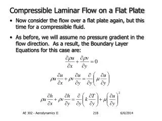
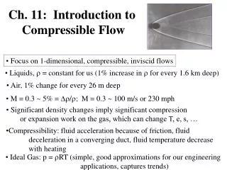
COMPRESSIBLE FLOW FRICTION Friction in gas pipelines
Coefficient • In pipelines of gasses flow functional reliance l = f(De,Re) is valid.It means ,that friction depend from the equivalent roughness and flow regime. • For steel material of gas pipes equivalent roughness De = 0,1 mm . • For copper or plastic gas pipes De = 0,0015–0,003 mm only.(see Table) • According the Moody chart,5 zones of friction factor is valid: • 1) Laminar flow.For laminar flow friction factor is independent of relative roughness,and can be estimated by formula: (1) Where : Re < 2000 –Reinold’s number;
For the transition II zone,(2000 < Re < 4000),the flow can be laminar or turbulent(or an unsteady mix of both) depending on the specific circumstances involved.Coefficient can be find according empirical formula Zaichenko: (2) • For the turbulent flow in hydraulically smooth pipe III zone(Re > 4000 ,and Re < 105,and Re e/d<10) the Blazius formula is fit: (3) • In the same III zone when pressure is medium or high and plastic pipes is used,the friction loss coefficient can be found: 70000 < Re < 700000 (4)
For flows with moderate values of Re in the turbulent IV zone(Re >4000, and 10 < Re e/d <500 ) coefficient depend on both - the Re number and relative roughness ( = f ( Re, e/d )).For this case the formula of Altshull- Kunigelis can be used: (5) • For the flows in the rough turbulent V zone(Re >4000, and • Re e/d >500) surface roughness completely dominates the character of the flow near the wall.( = f (e/d))From the (5) formula we can find in that case: (6)
Flow regime zones Minor pressure network Medium pressure network High pressure network I zone II zone III zone IV zone V zone 8 13 59 20 – – – 1 86 13 – – – 24 76 • NOTE: Even for hydraulically smooth pipes the friction factor is not zero.That is,there is a head loss in any pipe,no matter how smooth the surface is made.This is a result of the no-slip boundary conditions that requires any fluid to stick to any solid surface it flows over.There is always some microscopic surface roughness that produces the no-slip behavior on the molecular level, even when the roughness is considerably less then the viscous sub layer thickness. • According the practice and investigations of gas flow in pipelines it can be conclude that we can found all 5 flow resistance zones in steel gas pipe network. Table .Flow regimes in gas networks, in %
Turbulent flow regime in I.F.Moody diagram is characterized by a family of curves.The lowest curve of the family expresses - Re relationship for e/d = 0.It is a smooth pipe case – pipe wall roughness elements are hidden in a laminar film and the roughness makes no influence on the friction factor . • Each of the rest curves of the family represents definite relative roughness e/d.Thus, a friction factor here depends from both Re and e/d. • At the right side of the diagram the curves expressing = f(Re,e/d relationship are parallel to Re axis.It means that Re has no influence on , it depends on relative roughness e/d only.It is a rough pipe case. • Reynolds number Re and relative roughness e/d are to be known to read friction factor on the Moody diagram. When flow rate Q is computed and there is no possibility to compute Re , is read from a rough pipe zone of the chart.Then the actual meanings of Re is computed and friction factor is corrected.
Formulae of practical gas pipe network calculation • They are derived from the last ones when normal conditions of the gas flowing in the pipe linesis estimated: • n = 0,73 kg/m3; n = 14,310–6 m2/s; pn = 101,3 kPa • Re = (7) • Where : • Qn – gas flow rate in normal conditions,in m3/h. • When estimate that
and in the gas pipe line networks of minor pressure we can find: (8) , Here s = 6,473·10–9 d–4,75– an comparative pressure losses; Q – flow rate,in m3/h. • When we are calculated pressure losses of plastic pipelines in the medium or high pressure gas networks then:
(9) • After estimation that for natural gasses rn = 0,73 kg/m3, n = 14,3·10–6 m2/s one can found: (10) = 8,5010–4 (11) S 8,5010–4 d–4,806 Where: Qn – gas flow rate,in m3/h; p2 - pressure loss,in Pa2
The coefficients of minor loss in gas pipelines • These coefficients are found experimentally. • The meaning of minor coefficient depend on obstacle geometry and measurement as well as flow regimes.( influence of regimes is when Re < 105 and more significant - when laminar flow exist) • When the distance between neighboring elements of obstacles is small the impact on flow resistance can be .That must be estimated in the case by modification of minor coefficient . • The impact distance can be found by A.D.Altshul formula: lkl = 0,5 d . (12) Where: lkl – impact distance
When coefficient of minor loss is calculate the velocity is measured after obstacle in the cross-section. • According the formula one can found: When:< 0,05 p1 r1 = r2andQ1= Q2 . (13) • The triplex tap is assign to section with less flow rate when calculating • For gas network of town pv = (5 – 10)% of pL • For short and complicate inner gas pipelines all must be estimated.
SYMBOL MINOR LOSS COEFFICIENT Sudden contraction Triplex in the junction Triplex in the bend Triplex between the bend Quadrilateral junction Quadrilateral bend Rounded bend 900 Cork tapds = 15 20 Valved = 15 20 25, 32, 40 ≥ 50 Valved = 50–100 mm d = 175–200 mm d 300 mm 0,35 1 1,5 3,0 2 3 0,3 4 2 11 7 6 5 0,5 0,25 0,15