Download
1 / 67
670 likes | 836 Views
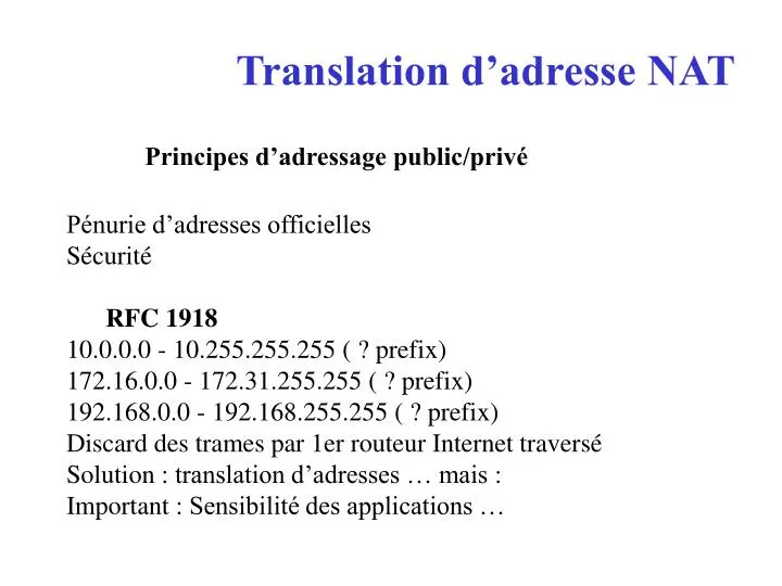
Translation d’adresse NAT. Principes d’adressage public/privé Pénurie d’adresses officielles Sécurité RFC 1918 10.0.0.0 - 10.255.255.255 ( ? prefix) 172.16.0.0 - 172.31.255.255 ( ? prefix) 192.168.0.0 - 192.168.255.255 ( ? prefix) Discard des trames par 1er routeur Internet traversé

E N D
Translation d’adresse NAT • Principes d’adressage public/privé • Pénurie d’adresses officielles • Sécurité • RFC 1918 • 10.0.0.0 - 10.255.255.255 ( ? prefix) • 172.16.0.0 - 172.31.255.255 ( ? prefix) • 192.168.0.0 - 192.168.255.255 ( ? prefix) • Discard des trames par 1er routeur Internet traversé • Solution : translation d’adresses … mais : • Important : Sensibilité des applications …
Network AddressTranslation Dans sa plus simple configuration, le NAT s’opère sur un routeur à 2 interfaces : une “ inside ” avec des adresses non autorisées ou non routées sur Internet qui doivent donc être translatées (converties) en adresses légales (officielles, publiques) avant de sortir vers l’extérieur (par la seconde interface : “ outside ”). NAT est défini notamment dans le RFC 1631
Inside local; Configured IP address assigned to a host on the inside network. Address may be globally unique, allocated out of the private address space defined in RFC 1918, or might be officially allocated to another organization. • Inside global; The IP address of an inside host as it appears to the outside network, "Translated IP Address." Addresses can be allocated from a globally unique address space, typically provided by the ISP (if the enterprise is connected to the global Internet). • Outside local; The IP address of an outside host as it appears to the inside network. • Outside global; The configured IP address assigned to a host in the outside network.
Principales caractéristiques • Static Address Translation • Etablissement d’un mapping un-pour-un entre adresses locales and globales • Dynamic Address Translation • Etablissement d’un dynamic mapping entre adresses locales and globales • Définition d’un pool d’adresses pour l’allocation des global addresses.Intéressant lorsque le nombre d’adresses officielles est inférieur au nombre d’adresses locales (fréquent). • Match Host • Affecter la même Host portion d’une IP Address et translater seulement le Network prefix. Utile pour identifier les users.
Port Address Translation (PAT) • Several internal addresses can be NATed to only one or a few external addresses by using a feature called Port Address Translation (PAT) which is also referred to as "overload," a subset of NAT functionality. • PAT uses unique source port numbers on the Inside Global IP address to distinguish between translations. Because the port number is encoded in 16 bits, the total number could theoretically be as high as 65,536 per IP address. PAT will attempt to preserve the original source port, if this source port is already allocated PAT will attempt to find the first available port number starting from the beginning of the appropriate port group 0-511, 512-1023, or 1024-65535. If there is still no port available from the appropriate group and more than one IP address is configured, PAT will move to the next IP address and try to allocate the original source port again. This continues until it runs out of available ports and IP addresses.
Destination Address Rotary Translation • A dynamic form of destination translation can be configured for some outside-to-inside traffic. Once a mapping is set up, a destination address matching one of those on an access list will be replaced with an address from a rotary pool. Allocation is done in a round-robin basis, performed only when a new connection is opened from the outside to the inside. All non-TCP traffic is passed untranslated (unless other translations are in effect). • This feature was designed to provide protocol translation load distribution. It is not designed to be used as a substitute technology for Cisco's LocalDirector product. Destination address rotary translation should not be used to provide Web service load balancing because it knows nothing about service availability. As a result, if a Web server were to become offline, the destination address rotary translation feature would continue to send requests to the downed server.
Limites du NAT Traffic Types/Applications supportés Tout TCP/UDP traffic qui ne comporte pas de source and/or destination IP addresses dans la partie application de la trame. + Applications avec « verrue NAT » HTTP TFTP telnet … Problème résiduel: Netmeeting v3 …
Conclusions: Eviter NAT au sein d’une même entreprise Cas des fusions de 2 sociétés Pérennité de connectivité ?? Redéfinition d’un nouveau plan d’adressage : lourd mais préférable
Cisco Configuration Commands • Interface Configuration Commands • ip nat { inside | outside } • Interfaces need to be marked whether they are on the inside or the outside. • Global Configuration Commands: Defining a pool • ip nat pool <name> <start-ip> <end-ip> { netmask <netmask> • | prefix-length <prefix-length> } [type {rotary}] • Defines a pool of addresses using start address, end address, and netmask. These addresses will be allocated as needed.
Enabling translation of inside source addresses • ip nat inside source { list <acl> pool <name> [overload] | • static <local-ip><global-ip> } • The first form enables dynamic translation. Packets from addresses that match those on the simple access list are translated using global addresses allocated from the named pool. The optional keyword overload enables port translation for UDP and TCP. The term overload is equivalent to Port Address Translation (PAT). • The second form of the command sets up a single static translation.
Enabling translation of inside destination addresses • ip nat inside destination { list <acl> pool <name> | • static <global-ip> <local-ip> } • Commande similaire à la « source translation command ». • For dynamic destination translation to make any sense, the pool should be a rotary-type pool. (option rotary dans l’IP nat pool correspondant). • Mais quel besoin ? ? ? voir le dernier exemple de ce chapitre …
Enabling translation of outside source addresses • ip nat outside source { list <acl> pool <name> | static <global-ip> <local-ip> } • The first form (list..pool..) enables dynamic translation. Packets from addresses that match those on the simple access list are translated using local addresses allocated from the named pool. • The second form (static) of the command sets up a single static translation. • Quel besoin : par exemple cas d’un réseau outside de même adresse réseau que le réseau inside …cas d’une société qui n’aurait pas choisi des adresses officielles ou conformes au RFC1918…
Configuring translation timeouts • ip nat translation timeout <seconds> • Dynamic translations time out after a period of non-use. When port translation is not configured, translation entries time out after 24 hours. This time can be adjusted with the above command or the following variations: • ip nat translation udp-timeout <seconds> • ip nat translation dns-timeout <seconds> • ip nat translation tcp-timeout <seconds> • When port translation is configured, there is finer control over translation entry timeouts, because each entry contains more context about the traffic using it. Non-DNS UDP translations time out after 5 minutes; DNS times out in 1 minute. TCP translations time out after 24 hours.
Exec Commands • Show active translations • show ip nat translations [ verbose ] • Show translation statistics • show ip nat statistics • Clearing dynamic translations • clear ip nat translation * • Clears all dynamic translations. • clear ip nat translation <global-ip> • Clears a simple translation. • clear ip nat translation <global-ip> <local-ip> <proto> <global-port> <local-port> • Clears a particular dynamic translation.
Debugging • debug ip nat [ <list> ] [ detailed ]
Exemples de Configuration • The following sample configuration translates between inside hosts addressed from either the 192.168.1.0 or 192.168.2.0 nets to the globally-unique 171.69.233.208/28 network. • La translation ne concerne que ces 2 seuls réseaux.
ip nat pool net-20 171.69.233.209 171.69.233.223 netmask 255.255.255.240 ip nat inside source list 1 pool net-20 ! interface Ethernet0 ip address 171.69.232.182 255.255.255.240 ip nat outside ! interface Ethernet1 ip address 192.168.1.94 255.255.255.0 ip nat inside ! access-list 1 permit 192.168.1.0 0.0.0.255 access-list 1 permit 192.168.2.0 0.0.0.255
The next sample configuration translates between inside hosts addressed from the 9.114.11.0 net to the globally unique 171.69.233.208/28 network. Packets from outside hosts addressed from 9.114.11.0 net (the "true" 9.114.11.0 net) are translated to appear to be from net 10.0.1.0/24. Cas d’une société qui n’aurait pas choisi comme adressage interne un adressage public ou conforme au RFC1918.
ip nat pool net-20 171.69.233.209 171.69.233.223 netmask 255.255.255.240 ip nat pool net-10 10.0.1.1 10.0.1.254 netmask 255.255.255.0 ip nat inside source list 1 pool net-20 ip nat outside source list 1 pool net-10 interface Ethernet0 ip address 171.69.232.182 255.255.255.240 ip nat outside interface Ethernet1 ip address 9.114.11.39 255.255.255.0 ip nat inside ! access-list 1 permit 9.114.11.0 0.0.0.255 La translation ne concerne que ce seul réseau.
Configuration du pool: • The pool configuration syntax has been extended to allow discontiguous ranges of addresses • : ip nat pool <name> { netmask <mask> | prefix-length <length> } • This command will put the user into IP NAT Pool configuration mode, where a sequence of address ranges can be configured. There is only one command in this mode: • address <start> <end> • Router(config)#ip nat pool fred prefix-length 24 • Router(config-ipnat-pool)#address 171.69.233.225 171.69.233.226 • Router(config-ipnat-pool)#address 171.69.233.228 171.69.233.238 • This configuration creates a pool containing addresses 171.69.233.225-226 and 171.69.233.228-238 (171.69.233.227 has been omitted).
Translating to interface's address • As a convenience for users wishing to translate all inside addresses to the address assigned to an interface on the router, the NAT code allows one to simply name the interface when configuring the dynamic translation rule: • ip nat inside source list <number> interface <interface> overload • If there is no address on the interface, or it the interface is not up, no translation will occur. • Example: • ip nat inside source list 1 interface Serial0 overload
Static translations with ports: • Services on the inside network (like mail) will require additional configuration. This command allows the user to map certain services of certain inside hosts. • ip nat inside source static { tcp | udp } <localaddr> <localport> <globaladdr> <globalport> • Example: • ip nat inside source static tcp 192.168.10.1 25 171.69.232.209 25
Translation Entry Limit • Using the following command, Cisco IOS NAT can be configured to limit the number of translation entries it creates. • The default is that there is no limit. • ip nat translation max-entries <n>
Provide TCP Load Distribution • Another use of NAT is unrelated to Internet addresses. Your organization may have multiple hosts that must communicate with a heavily used host. Using NAT, you can establish a virtual host on the inside network that coordinates load sharing among real hosts. Destination addresses that match an access list are replaced with addresses from a rotary pool. Allocation is done in a round-robin basis, and only when a new connection is opened from the outside to the inside. Non-TCP traffic is passed untranslated (unless other translations are in effect).
The router performs the following process when translating rotary addresses: • 1.The user on Host B (9.6.7.3) opens a connection to virtual host at 1.1.1.127. • .The router receives the connection request and creates a new translation, allocating the next real host (1.1.1.1) for the inside local IP address. • .The router replaces the destination address with the selected real host address and forwards the packet. • .Host 1.1.1.1 receives the packet and responds. • .The router receives the packet, performs a NAT table lookup using the inside local address and port number, and the outside address and port number as the key. The router then translates the source address to the address of the virtual host and forwards the packet. • The next connection request will cause the router to allocate 1.1.1.2 for the inside local address.
Note The access list must permit only those addresses that are to be translated. (Remember that there is an implicit "deny all" at the end of each access list.) An access list that is too permissive can lead to unpredictable results. In the following example, the goal is to define a virtual address, connections to which are distributed among a set of real hosts. The pool defines the addresses of the real hosts. The access list defines the virtual address. If a translation does not already exist, TCP packets from serial 0 (the outside interface) whose destination matches the access list are translated to an address from the pool.
ip nat pool real-hosts 192.168.15.2 192.168.15.15 prefix-length 28 type rotary ip nat inside destination list 2 pool real-hosts ! interface serial 0 ip address 192.168.15.129 255.255.255.240 ip nat outside ! interface ethernet 0 ip address 192.168.15.17 255.255.255.240 ip nat inside ! access-list 2 permit 192.168.15.1
Firewall – Pare-feux • Caractéristiques générales et offre du marché • Firewall applicatifs basé sur PC + OS connu (Unix, NT, Win2K, …) • Exemple : Firewall-1 de Checkpoint Software • Firewall basé sur boitier standalone et OS propriétaire • Exemple : PIX Cisco • Offre Cisco : Cisco PIX 501 • IOS firewall pour routeur Cisco (mémoires requises)
Le Cisco ASA succède au PIX, le boîtier firewall et VPN le plus vendu au monde. Le suivi de l’évolution des menaces requiert toujours plus de puissance et de débit. Un firewall doit pouvoir filtrer le contenu du trafic, notamment bloquer les virus, spyware, et spams. En outre, le développement de la mobilité professionnelle crée des nouveaux besoins de connexion à distance simplifiés et sécurisés en SSL. L’ASA a été pensé pour fournir ces nouveaux services, dans une plateforme évolutive, parce que toutes les sociétés n’ont pas les mêmes besoins de sécurité.
- L’ASA se base sur le moteur Firewall et VPN IPSec du PIX auxquels s’ajoutent des nouveaux services tels que : • l´accès distant en VPN SSL • la technologie IPS , détection et prévention d’intrusion • l’Anti-X : anti-virus, anti-spyware, anti-phishing, anti-spam, blocage d’URL… • NAC (Network Admission Control) : authentification, autorisation et vérification de la sécurité des machines qui accèdent au réseau en SSL.- l’ASA est optimisé pour filtrer des services applicatifs de nouvelle génération sans dégradation de la qualité de service, en particulier des flux voix et vidéo.- Il est fourni avec une interface logicielle d’administration graphique de toute nouvelle génération, ASDM 6.0, qui simplifie la vie de l’administrateur
PIX Cisco • OS Similaire à IOS Cisco mais ce n’est pas un IOS, commandes différentes • Modes d’accès : identique IOS • Unprivileged mode : ">" prompt. • Privileged mode : t "#" • Enable,disable, exit, or quit • Configuration mode "(config)#" prompt avec la commade configure terminal • 0 represents 0.0.0.0. • Backups • write memory • tftp-server,write net
Configuration des Interfaces du Firewall • Assignation des IP Address and Subnet Mask • ip address inside ip_address netmask • ip address outsideip_address netmask • Exemple: • ip address inside 192.168.1.1 255.255.255.0
Changer les noms d’Interface et les Security Levels (optionnel) • nameif ethernet0 outside security0 (default) • nameif ethernet1 inside security100 (default) • nameif ethernet2 intf2 security10 (default) • Show nameif • Donner des noms significatifs : exemple : dmz1 • Niveaux de sécurité : 100 est maximale, 0 minimale • Ils servent à contrôler les accès entre les systèmes des différentes interfaces.
Principes • Pour accéder à une interface de basse sécurité depuis une interface de sécurité haute utiliser les commandes nat et global (voir exemples qui suivent). Par défaut pas de restriction (si une commande nat est activée). Utiliser des access-list pour restreindre les droits (selon l’adresse IP et/ou le port TCP/UDP). • Remarques : implicit deny (permit) all existe comme avec IOS. Le wildcard mask n’est pas utilisé on utilise le maque “ normal ”
Pour accéder à un interface de haute sécurité depuis une interface de sécurité basse utiliser les commandes static et access-list (voir exemples qui suivent). Par défaut tout est interdit. • Remarques : dans les anciennes versions de PIX software (< v5), la commande conduit était utilisée (au lieu de l’access-list).
Configuring the PIX Firewall for Routing • route outside 0 0 209.165.201.2 1 (route par defaut) • route inside 192.168.5.0 255.255.255.0 192.168.0.2 1 • route dmz4 192.168.6.0 255.255.255.0 192.168.4.2 1 • 1 = next hop
Routeur @ 209.165.201.2 @ Outside: 209.165.201.2 DMZ 192.168.4.1 PIX 192.168.4.2 Routeur 192.168.6.1 Inside: 192.168.0.1 192.168.0.2 192.168.5.1
Etablir la connectivité Outbound avec NAT et PAT • Network Address Translation (NAT). • Port Address Translation (PAT) avec une seule globale IP address • 64,000 ports sont en théorie disponibles (port codé sur 16 bits) • Le PIX Firewall associe une adresse interne avec une adresse globale en utilisant un NAT identifier (NAT ID).
Ajouter une nat commandepour chaque interface de plus haut niveau de securité depuis laquelle vous voulez que des users puissent initialiser des connexions vers des interfaces de niveau de sécurité inférieur : • To let inside users start connections on any lower security interface, use the nat (inside) 1 0 0 command. • To let dmz4 users start connections on any lower security interface such as dmz3, dmz2, dmz1, or the outside, use the nat (dmz4) 1 0 0 command. • Instead of specifying "0 0," to let all hosts start connections, you can specify a host or a network address and mask. • For example, to let only host 192.168.2.42 start connections on the dmz2 interface, you could specify the following: • nat (dmz2) 1 192.168.2.42 255.255.255.255
LE "1" après l’interface est le NAT ID. NAT ID 0 means to disable Network Address Translation. Le NAT ID in the nat command has to be the same NAT ID you use for the corresponding global command. global (outside) 1 209.165.201.5 netmask 255.255.255.224 global (outside) 1 209.165.201.10-209.165.201.20 netmask 255.255.255.224
The first global command statement specifies a single IP address, which the PIX Firewall interprets as a PAT. The PAT lets up to 65,535 hosts start connections to the outside. PIX Firewall permits one PAT global command statement for each interface. The second global command statement augments the pool of global addresses on the outside interface. The PAT creates a pool of addresses used only when the addresses in the first global command statement are in use.
global (dmz1) 1 192.168.1.10-192.168.1.100 netmask 255.255.255.0 global (dmz2) 1 192.168.2.10-192.168.2.100 netmask 255.255.255.0 The global command statement for dmz1 lets users on the inside,dmz2, dmz3, and dmz4 start connections on the dmz1 interface. The global command statement for dmz2 lets users on the inside, dmz3, and dmz4 start connections on the dmz2 interface. If you use network subnetting, specify the subnet mask with the netmask option.
You can track usage among different subnets by mapping different internal subnets to different PAT addresses. For example: nat (inside) 1 10.1.1.0 255.255.255.0 nat (inside) 2 10.1.2.0 255.255.255.0 global (outside) 1 192.168.1.1 global (outside) 2 209.165.200.225 In this example, hosts on the internal network 10.1.1.0/24 are mapped to global address 192.168.1.1, and hosts on the internal network 10.1.2.0/24 are mapped to global address 209.165.200.225 in global configuration mode.
Example 1: Two Interfaces Without NAT nameif ethernet0 outside security0 nameif ethernet1 inside security100 interface ethernet0 10baset interface ethernet1 10baset ip address outside 209.165.201.3 255.255.255.224 ip address inside 192.168.3.254 255.255.255.0 hostname pixfirewall arp timeout 14400 no failover logging buffered debugging nat (inside) 0 192.168.3.0 255.255.255.0 route outside 0.0.0.0 0.0.0.0 209.165.201.1 1 access-list ping_acl permit icmp any any access-group ping_acl in interface inside access-group ping_acl in interface outside mtu outside 1500 mtu inside 1500