Download
1 / 24
240 likes | 358 Views
MHD Issues and Control in FIRE. C. Kessel Princeton Plasma Physics Laboratory Workshop on Active Control of MHD Stability Austin, TX 11/3-5/2003. Layout of FIRE Device. R=2.14 m a=0.595 m x =2.0 x =0.7 P fus =150 MW. PF4. PF1,2,3. H-mode Ip=7.7 MA B T =10 T N =1.85

E N D
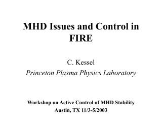
MHD Issues and Control in FIRE C. Kessel Princeton Plasma Physics Laboratory Workshop on Active Control of MHD Stability Austin, TX 11/3-5/2003
Layout of FIRE Device R=2.14 m a=0.595 m x=2.0 x=0.7 Pfus=150 MW PF4 PF1,2,3 H-mode Ip=7.7 MA BT=10 T N=1.85 li(3)=0.65 flat=20 s AT-mode Ip=4.5 MA BT=6.5 T N=4.2 li(3)=0.40 flat=31 s TF Coil CS3 Cu stabilizers PF5 CS2 CS1 Cu cladding VV
FIRE Description R = 2.14 m, a = 0.595 m, x = 2.0, x = 0.7, Pfus = 150 MW • H-mode • IP = 7.7 MA • BT = 10 T • N = 1.80 • = 2.4% • P = 0.85 • = 0.075% • q(0) < 1.0 • q95 ≈ 3.1 • li(1,3) = 0.85,0.66 • Te,i(0) = 15 keV • n20(0) = 5.3 • n(0)/n = 1.15 • p(0)/p = 2.4 • AT-Mode • IP = 4.5 MA • BT = 6.5 T • N = 4.2 • = 4.7% • P = 2.35 • = 0.21% • q(0) ≈ 4.0 • q95, qmin ≈ 4.0,2.7 • li(1,3) = 0.52,0.45 • Te,i(0) = 15 keV • n20(0) = 4.4 • n(0)/n = 1.4 • p(0)/p = 2.5 Cu passive plates plasma Port Cu cladding
FIRE H-mode Parameters and Profiles total bootstrap
FIRE H-mode: m=1 Stability • Sawteeth • Unstable, r/a(q=1) ≈ 0.33, Porcelli sawtooth model in TSC indicates weak influence on plasma burn due to pedestal/bootstrap broadening current profile, and rapid reheat of sawtooth volume • Requires ≥ 1 MA of off-axis current to remove q=1 surface • RF stabilization/destabilization of sawteeth? To remove or weaken drive for low order NTM’s
FIRE H-mode: Neo-Classical Tearing Modes • Neo-Classical Tearing Modes • Unstable or Stable? • Flattop time (20 s) is 2 current diffusion times, j() and p() are relaxed • Sawteeth and ELM’s as drivers are expected to be present • Operating points are at low N and P, can they be lowered further and still provide burning plasmas ----> yes, lowering Q • EC methods are difficult in FIRE H-mode due to high field and high density (280 GHz to access Ro) • LH method of bulk current profile modification can probably work, but will involve significant power, affecting achievable Q ----> is there another LH method such as pulsing that needs less current?
FIRE H-mode: Neo-Classical Tearing Modes TSC-LSC simulation POPCON shows access to lower N operating points (3,2) surface P(LH)=12.5 MW I(LH) = 0.65 MA n/nGr = 0.4
FIRE H-mode: Ideal MHD Stability • n=1 external kink and n=∞ ballooning modes • Stable without a wall/feedback • Under various conditions; sawtooth flattened/not flattened current profiles, strong/weak pedestals, etc. N≈3 • EXCEPT in pedestal region, ballooning unstable depending on pedestal width and magnitude • Intermediate n peeling/ballooning modes • Unstable, primary candidate for ELM’s • Type I ELM’s are divertor lifetime limiting, must access Type II, III, or other lower energy/higher frequency regimes • FIRE has high triangularity (x = 0.7) and high density (n/nGr < 0.8), what active methods should be considered?
FIRE H-mode: Ideal MHD Stability Self consistent bootstrap/ohmic equilibria No wall N(n=1) = 3.25 N(n=∞) 4.5 Other cases with different edge and profile conditions yield various results -----> N ≈ 3
FIRE AT-mode: Operating Space Database of operating points by scanning q95, n(0)/n, T(0)/T, n/nGr, N, fBe, fAr Constrain results with installed auxiliary powers CD efficiencies from RF calcs pulse length limitations from TF or VV nuclear heating FW and divertor power handling limitations identify operating points to pursue with more detailed analysis
FIRE AT-mode: Neoclassical Tearing Modes • Neoclassical Tearing Modes • Stable or Unstable? • q() > 2 everywhere, are the (3,1), (5,2), (7,3), (7,2)….going to destabilize? If they do will they significantly degrade confinement? • Examining EC stabilization at the lower toroidal fields of AT • LFS launch, O-mode, 170 GHz, fundamental • 170 GHz accesses R+a/4, however, p e ≥ ce cutting off EC inside r/a ≈ 0.67 • LFS deposition implies trapping degradation of CD efficiency, however, Ohkawa current drive can compensate • Current required, based on (3,2) stabilization in ASDEX-U and DIII-D, and scaling with IPN2, is about 200 kA ----> 100 MW of EC power! Early detection is required • Launch two spectra with LHCD system, to get regular bulk CD (that defines qmin) and another contribution in the vicinity of rational surfaces outside qmin to modify current profile and resist NTM’s ----> this requires splitting available power
FIRE AT-mode: Neoclassical Tearing Modes J. Decker, MIT 145≤≤155 GHz -30o≤L≤-10o midplane launch 10 kA of current for 5 MW of injected power =149 GHz L=-20o Ro Ro+a Bt=6.5 T fce=182 fce=142 170 GHz Ro Ro+a Bt=7.5 T fce=210 fce=164 200 GHz Ro Ro+a Bt=8.5 T fce=238 fce=190
FIRE AT-mode: Neoclassical Tearing Modes =ce=170 GHz r/a(qmin) ≈ 0.8 r/a(3,1) ≈ 0.87-0.93 Does (3,1) require less current than (3,2)? Local *, *, Rem effects? 200 GHz is better fit for FIRE parameters Rays are launched with toroidal directionality for CD pe=ce Short pulse, MIT Rays are bent as they approach =pe
FIRE AT-mode: Ideal MHD Stability • n= 1, 2, and 3…external kink and n = ∞ ballooning modes • n = 1 stable without a wall/feedback for N < 2.5-2.8 • n = 2 and 3 have higher limits without a wall/feedback • Ballooning stable up to N < 6.0, EXCEPT in pedestal region ballooning instability associated with ELM’s • Specifics depend on po/p, H-mode or L-mode edge, pedestal characteristics, level of LH versus bootstrap current, and Ip (q*) • FIRE’s RWM stabilization with feedback coils located in ports very close to the plasma, VALEN analysis indicates 80-90% of ideal with wall limit for n=1 • n = 1 stable with wall/feedback to N’s around 5.0-6.0 depending on edge conditions, wall location, etc. • n = 2 and 3 appear to have lower N limits in presence of wall, possibly blocking access to n = 1 limits ----> how are these modes manifesting themselves in the plasma when they are predicted to be linear ideal unstable? • Intermediate n peeling/ballooning modes • Unstable under H-mode edge conditions
FIRE AT-mode: Ideal MHD Stability H-mode edge Ip = 4.8 MA BT = 6.5 T N = 4.5 = 5.5% p = 2.15 li(1) = 0.44 li(3) = 0.34 qmin = 2.75 p(0)/p = 1.9 n(0)/n = 1.2 N(n=1) = 5.4 N(n=2) = 4.7 N(n=3) = 4.0 N(bal) > 6.0*
FIRE AT-mode: Ideal MHD Stability L-mode edge Ip = 4.5 MA BT = 6.5 T N = 4.5 = 5.4% p = 2.33 li(1) = 0.54 li(3) = 0.41 qmin = 2.61 p(0)/p = 2.18 n(0)/n = 1.39 N(n=1) = 6.2 N(n=2) = 5.2 N(n=3) = 5.0 N(bal) > 6.0*
AT Equilibriumfrom TSC-LSC Dynamic Simulations TSC-LSC equilibrium Ip=4.5 MA Bt=6.5 T q(0)=3.5, qmin=2.8 N=4.2, =4.9%, p=2.3 li(1)=0.55, li(3)=0.42 p(0)/p=2.45 n(0)/n=1.4 Stable n= Stable n=1,2,3 with no wall L-mode edge √V/Vo
FIRE AT-mode: Ideal MHD Stability Growth Rate, /s N=4.2 N RWM Feedback Coil ICRF Port Plug
FIRE H-mode and AT-Mode: Other • Alfven eigenmodes and energetic particle modes • Error fields from coil misalignments, etc. ----> install Cu window coils outside TF coil, stationary to slow response • Disruptions ----> • Pellet and gas injectors will be all over the device, resulting radiative heat load is high • Up-down symmetry implies plasma is at or near the neutral point, not clear if this can be used to mitigate or avoid VDE’s • Vertical position control • Cu passive stabilizers providing growth time of ≈ 30 ms, vertical feedback coils located outside inner VV on outboard side • Fast radial position control, antenna coupling, provided by same coils as vertical control • Shape control provided by PF coils
FIRE H-mode and AT-mode: Other PF4 PF1,2,3 Error correction coils TF Coil CS3 PF5 CS2 CS1 Fast vertical and radial position control coil