Download
1 / 23
230 likes | 251 Views
This text introduces the protection scheme for the SIS300 dipole string, covering dipole description, powering and protection scheme, quench heaters, diode stack, and expected radiation levels.

E N D
Protection scheme of the SIS300_Introduction Protection for SIS300 dipole string - Dipole description (Cross section, cable) - Powering and protection scheme (Dump resistors, quench heaters, diodes) - Quench heaters - Diode stack - Irradiation experiments on diodes - Expected level of radiation in SIS300 (first guess) - For the bent dipole: could we come to protection scheme with only dump resistors? - Conclusions E. Floch.GSI Quench expert meeting. Sep 2006
SIS 300 dipole cross section As given in the FBTR in April 2006 (FAIR Baseline Technical Report) Cross section proposed by CERN 4 pairs of bus bars (1 dipole string , 3 quadrupole strings) E. Floch.GSI Quench expert meeting. Sep 2006
Cable for SIS300 dipoles and quadrupoles Base: LHC outer cable (36 strands of 0.825 mm diameter) New: 316L core (25 mm thick), CuMn interfilamentary matrix GSI has enough cable (with a SS core and Cu Matrix) to built a 1 m dipole model -For LHC : 130 < RRRCu < 280 with an average value of 210 -Assume the same for SIS300 copper in the strands -Magnet protected with quench heaters, Tmax increases when RRR increases -For Tmax calculations we take RRR=RRRCu = 280 E. Floch.GSI Quench expert meeting. Sep 2006
Influence of the CuMn interfilamentary matrix At cold (10K): - the current flows only in Cu - the power dissipated in a cable with CuMn is 2.6 times higher than in a cable with only Cu Above 70 K: - the current starts to flow in CuMn - this effect must be taken into account when computing Tmax E. Floch.GSI Quench expert meeting. Sep 2006
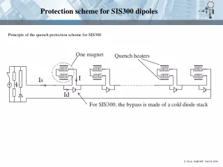
Quench protection schemes for a magnet string E. Floch.GSI Quench expert meeting. Sep 2006
3 power supply units and 6 dump resistors SIS 300 I0 = 6615 A Vpower supply = 681 V Rdi*I0/2 = 511 V for = 4 s E. Floch.GSI Quench expert meeting. Sep 2006
Quench heaters on LHC dipoles LHC "double dipole". -Each pole has two sets of quench heaters. -1 set made of 2 HF (high field) strips connected in series -1 set made of 2 LF (low field) strips connected in series -During normal operation all the HF heaters are powered simultaneously -LF heaters will replace "sick" HF heaters E. Floch.GSI Quench expert meeting. Sep 2006
Quench heaters on LHC dipoles LHC dipole half pole Layer of Kapton which houses the quench heaters Heaters made of 304 or 316L steel E. Floch.GSI Quench expert meeting. Sep 2006
Choice of the quench heaters for SIS300 SIS300 LHC LHC SIS300 The heater strip will use: -the same material (304 or 316 L) -the same thickness (25 m) -the same insulation E. Floch.GSI Quench expert meeting. Sep 2006
Computation of Tmax for the model dipole Computations done here for the model dipole whose cable has only a Cu matrix RRR=200, Vpf = 5.2 m/s, heaters are fired on both poles (total of heated turns nq = 32, 16 per pole) Quench heaters are designed so that -if one of the two heater sets fails (i.e only one pole is heated) -the magnet is still protected E. Floch.GSI Quench expert meeting. Sep 2006
Quench heaters when using a cable with CuMn E. Floch.GSI Quench expert meeting. Sep 2006
Cold diode stack for the SIS300 dipole Principle of the quench protection scheme for SIS100 During ramp up: Vdipole = L*dI/dt = 38 V Use of 8 LHC diodes in series For diode stack, D. Hagedorn and A. Gharib (CERN) measured: Vturn on_4.2 K = 8*5.71 = 45.6 V E. Floch.GSI Quench expert meeting. Sep 2006
LHC diode mounting for a dipole LHC dipole cold mass with its diode box I0 = 13000 A , = 105 s => Ediode = 1.4 MJ heat sink LHC dipole diode mounting With the copper heat heat sinks: Tmax_wafer < 300 K (wafer destruction at 450 K) E. Floch.GSI Quench expert meeting. Sep 2006
Radiation harness of LHC diodes -The diode forward (Vf) and reverve (Vr) voltages are affected by: the neutron fluence (F in n/cm2) and the accumulated dose (D in Gy) -Knowing Vf(I,F,D,T) is needed to compute the wafter maximum temperature Tw_max (destruction of the wafer at 450 K, one tries to keep Tw_max below 300 K -CERN study (D. Hagedorn) demonstrated that measuríng Vf(I,F.D) at 77 and 300 K enables to compute Vf(I,F,D) over all the temperature range -CERN (D. Hagedorn) measured Vf(I,F.D) at 77 and 300 K up to 2.8E13 n/cm2 and 2 kGy (correspond to what is expected after 20 years of LHC operation) -In 2004, not knowing what would be the radiation level in the SIS300 GSI decided to irradiate LHC diodes up to 1E14 n/cm2 (3 times more than CERN) -This new irradiation procedure took place at ITEP (Moscow) in 2006 E. Floch.GSI Quench expert meeting. Sep 2006
Irradiation set-up (ITEP, Moscow) -The neutrons were produced by irradiating one Tungsten target with a proton beam having an intensity of 1.6 GeV - 6 irradiation steps up to the target of 1E14 n/cm2 -Measure of Vf(I) and Vr on the 6 diodes at 77 K after each irradiation step -The 3 lower diodes (4,5,6) always stay at 77 K -Diodes (1,2,3) are annealed (at 300 K) after each irradiation step (measured at 300 K, placed again at 77 K and measured again) E. Floch.GSI Quench expert meeting. Sep 2006
Effect of radiation and annealing on Vf (I, 77K) E. Floch.GSI Quench expert meeting. Sep 2006
Temperature profile across the diode stack during the by-pass operation with irradiated diodes (up to 1.8E14 n/cm2) Current seen by the diode stack: I = I0 * exp (-t/Tau) with I0 = 6615 A and Tau = 4.8 s Calculations made by D. Hagedorn (CERN) - Tw = Twafer < 280 K => no risk of destruction which would occur at 450 K E. Floch.GSI Quench expert meeting. Sep 2006
What would be the level of radiation in SIS300 ? Study done on one singel magnet (E. Mustafin, GSI, L.N: Latyscheva, Russia, 2005) The computation assumes: -238U ions that irradiate the inner surface of the vacuum chamber -a gazing incidence of 1 mrad -incidence points are uniformly distributed over the length of the vacuum chamber as well as over the transverse azimutal angle (0 < < 2 ) There are 2 operating modes: - the CBM mode with 37 GeV/u - the RIB mode with 1 GeV/u ( 3 m is the magnet length) Next question: how ions are lost per year ? E. Floch.GSI Quench expert meeting. Sep 2006
What would be the level of radiation in SIS300 ? -According to P.Spiller (GSI), there should be no radiation problem before the extraction points (the beam is very well guided) -The SIS100 extraction scheme was finalized in spring 2006. The guess is that 5 % of the beam would be lost and distributed over the 30 m after the extraction point. -Let's take the same assumption for SIS300 -A life time of 1.1 year for a diode is not acceptable -A first solution is to equip the magnets after the extraction points with warm bypass E. Floch.GSI Quench expert meeting. Sep 2006
Disadvantages of using diodes and alternatives Disadvantages of using diodes: - they are radiation sensitive and we do not know what level of radiation is expected in the SIS300 - the LHC diode pots collect metallic dust (created by welding) which leads to short-circuits between coil and . ground - placing the diode pot below the cold mass (like for LHC) obliges to have a cryostat with a central foot - we must make sure that the temperature in the diode stack is stable and bubbles of gaz must be avoided - every diode stack needs to be tested at cold before installation, all contact resistances (diode/heat sink) must be . carefully checked, survey of the voltage characteristics, maintenance may be needed. Alternatives: - using warm bypasses every 4 magnets everywhere in the ring: - would be costly cryogenically - difficult to implement, warm by passes need switches that must be radiation protected (buildings up to 90 m . away, we would need to have very small niches or holes everywhere in the ring) - only use warm bypasses for the magnets after the extraction (more acceptable) - design new SIS300 magnets with a larger cable that would only require dump resistors like SIS100 E. Floch.GSI Quench expert meeting. Sep 2006
New SIS300 design with a larger cable Would be applied to the 4.5 T bent magnet with a single layer Possible larger cables: The MFISC was used to wind a 10 m LHC dipole that reached 10 T at 2 K after 2 quenches To find out if a larger cable can lead to a protection scheme having only dump resistors, we need to: - design the new dipole cross section (1rst design done by C. Mühle) - chose a filament diameter and fix the amount of CuMn in the interfalentary matrix and compute the losses - make the quench calculations with acceptable time constant for the current decrease (from 2 to 3 s) E. Floch.GSI Quench expert meeting. Sep 2006
Summary and conclusions For the straight SIS300 dipole (2 layers, 6615 A, 6 T), the protection scheme uses: - 6 dump resistors to dump the string current with a time constant of 4 s - a diode stack made of 8 diodes across each dipole - 2 sets of quench heaters per dipole. Heaters cover 20 turns per pole (for cable with CuMn) There is still an uncertainty on the level of radiation and the possibility of using cold diodes Protecting a magnet with only dump resistors has the following advantages: - no diodes (reduction in cost, increase of reliability, no maintenance on diodes, higher radiation level, smaller cryostat) - no quench heaters and their power supplies (reduction in cost, simplification of construction, save place in buildings) - lower cryogenic losses (lower energy dissipated during a quench, no "current" wires for quench heaters and diodes no voltage taps for diode, 8 wires will be saved) - no diode: possibility of using something else than a central post. For the new curved dipole (1 layer, 4.5 T): - we should investigate the possibility of using a larger cable which may enable . to protect the magnet string with only dump resistors E. Floch.GSI Quench expert meeting. Sep 2006
Related ducoments - FAIR/Protection_principles.cdr - SIS300_larger_cables.xls E. Floch.GSI Quench expert meeting. Sep 2006