Download
1 / 14
140 likes | 280 Views
HYBRIDS- construction . SUBSTRATES. CONSTRUCTION of composite SUBSTRATE - many lay-ups tried – best flatness obtained with: TPG central core 400um woven layer of CF prepreg each side oriented +-45 degrees 125um nominal

E N D
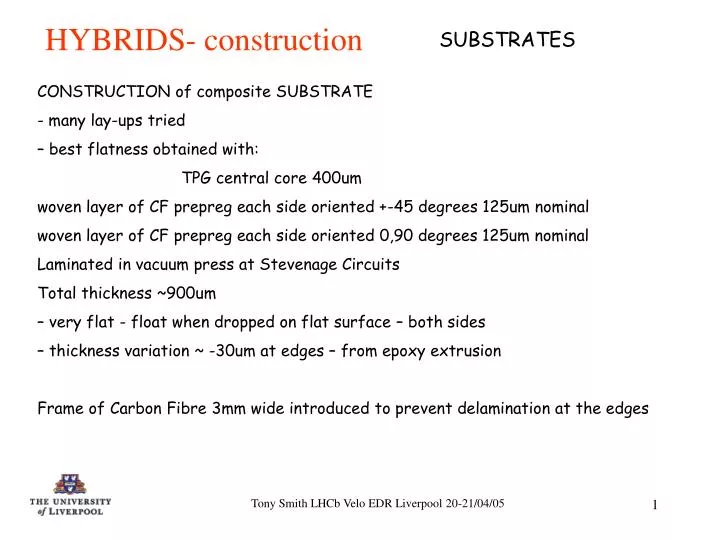
HYBRIDS- construction SUBSTRATES CONSTRUCTION of composite SUBSTRATE - many lay-ups tried – best flatness obtained with: TPG central core 400um woven layer of CF prepreg each side oriented +-45 degrees 125um nominal woven layer of CF prepreg each side oriented 0,90 degrees 125um nominal Laminated in vacuum press at Stevenage Circuits Total thickness ~900um – very flat - float when dropped on flat surface – both sides – thickness variation ~ -30um at edges – from epoxy extrusion Frame of Carbon Fibre 3mm wide introduced to prevent delamination at the edges Tony Smith LHCb Velo EDR Liverpool 20-21/04/05
HYBRIDS- construction SUBSTRATES 2 CONSTRUCTION of composite SUBSTRATE Frame of CF 3mm wide introduced to prevent de-lamination at the edges CF and TPG outlines shown in RED – the substrate is routed from the kit of these parts to the substrate profile shown in GREEN – the circuit is shown in BLUE Tony Smith LHCb Velo EDR Liverpool 20-21/04/05
HYBRIDS-construction CIRCUITS • Four copper layers with Kapton dielectrics bonded with 35um Espanex (modified polyimide) bondply – essentially a standard multilayer flexi circuit. • DESIGN RULES - not very tight for the technology good yield • 100um track and gap • 300um vias - 500um lands no buried vias • Layer material pressed copper thickness • thickness top bottom • solder resist 30 • copper foil 05+carrier 5um 5um ------- • SPB-050A Bond Ply 50um (was 35) -- -- • 2/3 SB1250 Cop/Clad flexi 60um 12um 12um • 12/50/12 (Adhesiveless) (power) • SPB-050A Bond Ply 50um (was 35) -- -- • 4 copper foil 05+carrier 5um -- 5um • total 200um (ground) • NB – plating thickness of ~8um Cu is added to top and bottom + Ni/Au on top Tony Smith LHCb Velo EDR Liverpool 20-21/04/05
HYBRIDS- construction CIRCUITS layout Component and trace layout Tony Smith LHCb Velo EDR Liverpool 20-21/04/05
HYBRIDS-construction Lamination to form a HYBRID Two CIRCUITS are now bonded back to back on the SUBSTRATES using the corner holes for alignment. The cut-outs in the corners allow for the differential expansion of the jig relative to the circuit and avoid stressing of the substrate when heated. Bonded using 50um bond Ply as in the circuit construction Total thickness = 900um (substrate) + 2* 50um (bondply) + 2*200um(circuits) = 1.4mm Note – K4s have had PA dowel and central tooling holes holes drilled in the substrate and circuit separately before lamination. For K5s, if Pitch Adapters are not to be fixed at the same time as the circuits are laminated, a third drilling step will drill these holes after lamination to give a cleaner finish. Tony Smith LHCb Velo EDR Liverpool 20-21/04/05
HYBRIDS-construction Pitch Adapters Pitch Adapter designs for Phi and R - need new fiducials for production. All locations are different, drawn in sets of 4 One complete set of Phi and R on one sheet 20 sets delivered today Ni/Au on Cu 22um min T&G Rfanout detector end Tony Smith LHCb Velo EDR Liverpool 20-21/04/05
Pitch adapters tested at Liverpool will be shipped to Stevenage circuits as “kits” of 8 pieces for lamination to hybrids in vacuum press. (to avoid air entrapment) Stevenage have confirmed they are willing to develop this. Details of jigging to be confirmed. Method: Bottom jig plate has pins loosely held (avoiding CTE mismatch stress) to match holes in bond-ply segments( DARK BROWN), PA segments(LIGHT BROWN) and hybrid (LIGHT BROWN AND BLUE) Packing pieces (GREEN) keep the assembly planar. Protection pad (RED) is shown with a cut-out but will have only holes for the pins Top jig plate (NOT SHOWN) would have loose holes for pins It is in principle possible to do this operation at the same time as the lamination of the circuits to the substrate. HYBRIDS-construction Pitch adapter attachment Tony Smith LHCb Velo EDR Liverpool 20-21/04/05
CIRCUITS + fanouts+ detectors HYBRIDS- construction Tony Smith LHCb Velo EDR Liverpool 20-21/04/05
HYBRIDS Population Tests on early prototypes showed that reflow soldering would produce distortions as the whole hybrid would be heated beyond the glass transition temperature of the adhesives without the hybrid being supported. It was therefore decided to Hand solder the components. Bond areas (and P.A.s when they are fitted) are masked to prevent solder splashes and damage. Three companies have quoted for this work. One (Hawk Electronics, Accrington UK) has populated 2.5 hybrids (no fanouts fitted) with good (visual) results. All three companies use a water removable flux and circuits are washed with a water based solvent and air dried at low temperature. First hybrids returned are not clean to the standard needed (some flux residues can be seen) and will be cleaned with Prozone, a solvent based PCB cleaner on return to Liverpool. (this has been used on the previous modules with good results). Tony Smith LHCb Velo EDR Liverpool 20-21/04/05
HYBRID- construction Detailed sequence 1 Hybrid construction sequence Liverpool – 1.1) TPG and CF Kits prepared and sent to Stevenage circuits 1.2) Sets (8 pieces) of tested Pitch Adapters (PA’s) sent to Stevenage Stevenage – 2.1) TPG and CF kits laminated in vacuum press to form substrate 2.2) Substrate profiled, drilled and routed (note 1) 2.3) Four layer kapton circuits produced, 2 per module 2.4) Circuits electrically tested before and after Ni/Au process 2.5) Circuits laminated to each side of substrate in vacuum press to produce hybrid 2.6) Mark one side of hybrid with sequence number in Red – R side 2.7) Post lamination electrical test of hybrid (if possible - note 2) 2.8) R and Phi PA’s attached to hybrids in vacuum press 2.9) Completed hybrids sent to Liverpool Tony Smith LHCb Velo EDR Liverpool 20-21/04/05
HYBRID- construction Detailed sequence 2 Tony Smith LHCb Velo EDR Liverpool 20-21/04/05
HYBRIDS – testing (K4) HT TEST Hybrid + short cable tested together in Vac Tank Hybrid populated with decoupling caps (2*500v 10nf to Gnd) Guard and HT shorted together All lines except HT and Guard on HT connector shorted to ground (includes Power) Discharges (brief – up to 15nA ) seen on ramping up above 430V 0.4nA leakage at 500V for 1 hour 0.2nA leakage at 500V if taken to 510 and back down again. holds 500V but need more statistics K5 clearances are the same as K4 so no differences expected Tony Smith LHCb Velo EDR Liverpool 20-21/04/05
HYBRIDS – testing (K4) Performance • Three single sided modules have been successfully operated in November test beam. • No functional problems encountered with powering, configuring and reading out. • But there is readout pulse shape distortion caused by: • thickness constraint on modules and possibly cable geometry ( impedance mismatches) • Thin dielectrics on the hybrid high (~25pF) capacitance on 100mm of hybrid trace which loads the output drivers. • Impossible to obtain transmission line performance over the short (~100mm) trace length on the hybrid (drivers see a reactive rather than resistive load). This is essentially a fixed parameter constrained by dielectric thickness) • On exiting the hybrid the analog signals travel over a 300mm length through the short tails and then through the Nikhef long tails. • Simulations of the readout chain have been done by Jan Buytaert and we await these results before proceeding with cable fabrication. Tony Smith LHCb Velo EDR Liverpool 20-21/04/05
HYBRIDS – K4K5 Changes Numbered chips (0-F) for simpler reference when scanning under scope Put copper in corner tab area to stiffen it More and larger chip fiducials new F shapes orthogonal to bonder axes. New circular Fiducials for population Placement markers removed from under detector guard rails Split power plane into four and added decoupling caps between sections Add 3 new sense lines + resistors (0 ohms in 0V 100 ohms in power) Moved caps at side of chips for bonding side bonds Removed HT leak resistors Made HT filter resistors 0805s (100volt rating) or 1206(200V rating) HT caps return to ground not HT ret Moved components HT inwards Power on reset to uses old DAV pair 50 ohms to GND on return side of the pair. Two semitek temp sensors at bottom and RHS RAD monitor pads provided at centre of RHS Move resistors next to connectors to allow removal tool to be used PA’s ----- areas still neededfor bonding off Fanout ------ fids are not regular and end up underneath bonds. Fanouts need larger fids Fanout ------ consult Mark + Mike on best fid design Tony Smith LHCb Velo EDR Liverpool 20-21/04/05