Download
1 / 27
2.22k likes | 6.16k Views
Membrane separation. Configuration.Modules.Transport.Fouling. FLAT - the active layer is a flat - synthesised as a continuous layer - low surface area per volume

E N D
Membrane separation Configuration.Modules.Transport.Fouling
FLAT - the active layer is a flat - synthesised as a continuous layer - low surface area per volume - used in flate-and-plate module and spiral-wound module TUBULAR - usually active layer is inside - the permeate crosses the membrane layer to the outside (feed inside) - high surface per volume - several lenghts and diameters (>10mm) Configuration
Membrane module – the unit into which the membrane’s area is packed. • Protects membranes against mechanical damage • Permits get high area in small volume Requirements for membrane: • High selectivity separation components • High permeability with respects to solvent M.M. have to be keep: • High productivity of process, • Leaktighness between stream of permeate and retentate in the high ratio of membrane surface to module’s volume, • Facility of cleaning and sterilization, • Low costs by itself • High resistance membrane on agressive chemical, physical & biological factors.
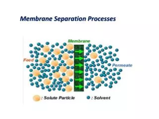
The module is the central part of membrane instalation. Feed composition and a flow rate inside the module will change as a function of distance. Permeate stream is the fraction of the feed stream of the feed stream which passes through the membrane. Retentate stream is the fraction retained on the membrane. SIMPLE MODULE
Plate-and-frame module Spiral-wound module Tubular module Capillary module Hollow-fiber module MEMBRANE MODULES
The choice of module configuration Based on economic considerations • Type of separation problem • Ease of cleaning • Ease of maintenance • Ease of operations • Compactness of the system • Scale • Possibility of membrane replacement
PLATE-AND-FRAME MODULE The number of sets needed for a given membrane area furnished with sealing ring and two end plates then builds up to a plate-and-framestack
Plate-and-frame module Schematic flow path in plate-and-frame module In order to reduce channeling- a tendency a flow along a fixed pathway and to establish as uniform flow distribution so-called ‘stop-discs’ Tortous-path plate Is used to improve mass transfer, to reduce concentration polarisation by applying a proper spacer material.
Advantages High allowable work pressure (high viscosity liquids) Easy to clean Easy to replace membranes Disadvantages Low membrane area per volume (100-400 m2/m3) Plate-and-frame module Electrodialysis, pervaporation, membrane destillation
SPIRAL-WOUND MODULE Membrane and permeate-side spacer material are glued along three edges build a membrane envelope. The feed flows axial through the cylindrical module parallel along the central pipe whereas the permeate flows radially toward the central pipe. Pressure vessel containig 3 spiral-wound modules arranged in series
Advantages -High packing density (300-1000m2/m3) - Easy and inexpensive to adjust hydronomics by changing feed spacer thickness to overcome conc. polarization and fouling - Low relative costs Disadvantages Difficult to cleaning and sterilization High pressure drop (100-150kPa) - Use only for pure medium Spiral-wound module
Tubular module Cross section of monolithic ceramic module Schematic drawing of tubular module The feed solution always flows through the centre of the tubes while the permeate flows through supporting tube into the module housing .
Advantages Resistance for fouling Easy to cleaning Disadvantages Low packing density (300m2/m3) Expensive Tubular module Reverse osmosis, ultrafiltration
Capillary module Capillary module consists of a large numbers of capillaries assembled together in a module. The free ends of the capillaries are potted agents such as epoxy resins, polyurethans.
CAPILLARY MODULE Two types of module arrangements can bedistinguised The choice between the two concepts is mainly based on the application where the parameters such a pressure, pressure drop, type of membrane available etc. are important. Depending on the concept chosen, asymmetric capillaries are used with their skin on the outside or inside
HOLLOW-FIBER MODULE The difference – dimmensions of the tubes, but module concepts are the same. The hollow-fiber module – highest packing density 30000m2/m3. A perforated central pipe is located in the center of the module through which the feed solution enters.
Hollow-fiber module Advantageous to use the ‘inside-out’ type to avoid increase in permeate pressure within the fibers and it’s thin selective top-layer is better protected, whereas a higher membrane area can be achieved with the ‘outside-in’ concept.
Advantages High packing density 500-9000 m2/m3 Low relative costs Disadvantages Poor resistance of fouling Difficult to clean Difficult to change the membrane Hollow-fiber module Microfiltration, ultrafiltration, reverse osmosis, pervaporation, liquid membranes and the membrane cofactors where the boundary layer resistance may become very important as well.
Membrane fouling Polarisation phenomena are reversible processes, but in practise, a continuous decline in flux decline can often be observed. Flux as a function of time. Both concentration polarization and fouling can be distinguished
The (ir)reversible deposition of retained particles, colloids, emulsions, suspensions, macromolecules, salts etc. on or in the membrane. The includes adsorption, pore blocking, precipitation and cake formation. Occurs in microfiltration and ultrafiltration. Pressure driven processes, type of separation and the type of membrane used to determine the extent of fouling. Depends: concentration, temperature, pH, ionic strenght, specific interactions (hydrogen bonding, dipole-dipole interactions) Membrane fouling
Membrane fouling Kozany – Carman relationship: Flux: ds– the ‘diameter’ of the solute particle where: Total cake layer resistance (Rc) - porosity of cake layer ms – the mass of the cake where: where: s – the density of the solute rc – specific resistance of the cake lc – cake thickness A – the membrane area The thickness of the layer depends on the type of solute and especially on operating conditions and time. The growing layer of accumulates results in a continuous flux decline.
Membrane fouling Rc the cake layer resistance can be obtained from the mass balance. In case of complete solute rejection: R = 100% The flux can be written: or Jw – pure water flux
Membrane fouling P Cb Reciprocal flux is indeed linearly related to the permeate volume V for various concentrations (Cb) and applied pressures (P) in an unstirred dead-end filtration experiment with BSA as solute. Reciprocal flux as a function of the permeate volume for different concentrations (1) and applied pressures (2)
Methods to reduce fouling • Pretreatment of the feed solution - heat treatment - pH adjustment - addition of complexing agents (EDTA etc.) - chlorination - adsorption onto active carbon - chemical clarification - premicrofiltration - preultrafiltration • Membrane properties • Module & process conditions • Cleaning - hydraulic cleaning ( back-flushing ) - mechanical cleaning - chemical cleaning - electric cleaning
Membrane fouling Alternate pressuring and depressuring and by changing the flow direction at a given frequency. After a given period of time, the feed pressure is released and the direction of the permeate reversed from the permeate side to the feed side in order to remove the fouling layer within the membrane or at the membrane surface. Flux versus time behaviour in a given microfiltration process with and without back-flushing


![Global Nitrogen Gas Separation Membrane Market [2016-2021]](https://cdn4.slideserve.com/7290090/slide1-dt.jpg)