Download
1 / 53
530 likes | 540 Views
A Parallel Algorithm for Hardware Implementation of Inverse Halftoning. Umair F. Siddiqi 1 , Sadiq M. Sait 1 & Aamir A. Farooqui 2 1 Department of Computer Engineering King Fahd University of Petroleum & Minerals, Dhahran 31261, Saudi Arabia 2 Synopsys Inc.

E N D
A Parallel Algorithm for Hardware Implementation of Inverse Halftoning Umair F. Siddiqi1, Sadiq M. Sait1 & Aamir A. Farooqui2 1Department of Computer Engineering King Fahd University of Petroleum & Minerals, Dhahran 31261, Saudi Arabia 2Synopsys Inc. Synopsys Module Compiler, Mountain View California, USA
Analog halftoning • The process of rendition of continuous tone pictures on media on which only two levels can be displayed. • The size of dots are adjusted according to the local print intensity. • When looked at a distance it gives the impression of the original picture.
Digital halftoning • In digital halftoning the input of the system is a grey-level image having more than two levels for example, 256 levels and the resulting image has only two levels. • The halftone image is comprised of zeros and ones but gives the impression of the original image from a distance.
Inverse halftoning • Inverse halftoning is the reconstruction of continuous tone picture (e.g. 256 levels) from its halftoned version. • The input to an inverse halftoning system in an image that consists of zeros and ones and output is an image in which each pixel have value from 256 gray-levels. • Inverse Halftoning finds application in image compression, printed image processing, scaling, enhancement, etc. • Inverse halftoning can be for color images but we are concerned with gray-level images and their halftones.
Example of Inverse Halftoning Halftone Image Inverse Halftone or grey-level image
Demonstration of our Inverse halftoning algorithm • The next few slides show how inverse halftone operation is performed in our algorithm.
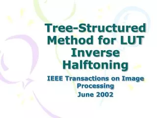
Lookup Table (LUT) based Inverse Halftone operation • The Lookup Table (LUT) method proposed by Mese and Vaidyanathan is used for inverse halftone operation. • The LUT method uses a template “19pels” to select pixels from the neighborhood of the pixel that is going to be inverse halftone. • This “19pels” then goes into a LUT which compares the “19pels” with its stored values and returns a gray-level for the input “19pels”.
“19pels” Template The pixel numbered 0 is the one going to be inverse halftoned This pattern is associated with each pixel that is to be inverse halftoned
Problem of parallel LUT inverse halftone operation • The LUT method uses one Lookup table that contains inverse halftone values for all “19pels” that are obtained through training set of halftones of standard images. • To fetch parallel inverse halftone values of more than one 19pels we need to implement multiple copies of the LUT !
Our approach to parallel LUT inverse halftoning • The single large LUT has been divided into many Smaller LUTs (SLUTs). • Now more than one 19pels can fetch its inverse halftone value from a separate SLUT independent to other parallel 19pels. • Next problem is to develop a method to send incoming 19pels to separate SLUTs.
Method to distinguish 19pels from each other • The task to send many incoming 19pels to their separate SLUTs is accomplished by defining an operator over 19pels. • This operator is called Relative XOR Change (RXC). • When all incoming 19pels are operated through this operator they convert into distinguished values in the range of –t to +t, where t = 19 in our case, but it could be any random integer within a suitable range with respect to total number of SLUTs and hardware complexity.
RXC Operator for Pn • Pn-1= “19pels” with the pixel 0 at position (row,col-1); • Pn= “19pels” with pixel 0 at position (row,col); • xor_1= XOR(Pn-1, Pn ); • Magnitude of RXC= |RXC|= Number of Ones(xor_1); • Sign of RXC= sgn(RXC)= + when |Pn| > |Pn-1| - when |Pn| < |Pn-1| Note: pixel 0 is the one that is to be inverse halftoned
RXC over gray-level halftones I Gray-level 230 Corresponding halftone obtained through Floyd and Steinberg Error Diffusion Method
RXC over gray-level halftones II Gray-level 130 Corresponding halftone obtained through Floyd and Steinberg Error Diffusion Method
Magnified look at the halftones I Gray-level 210 Gray-level 130 Halftone shows no column-wise periodicity among dots over small 19pels regions Halftone shows column-wise periodicity among dots over small 19pels regions
Magnified look at the halftones II Gray-level 120 Portion of the halftone from image Boat Halftone shows no periodicity among dots over small 1D 19pels regions Halftone shows no periodicity among dots over small 1D 19pels regions
NON Periodic Vibratory RXC Operator • The operator RXC has been defined that is simple to implement in hardware as well as gives NON periodic vibratory response over most of the gray levels from 0 to 255. • We have assumed that a gray level image is a composition of many gray levels and obtaining the performance of RXC over individual gray levels can give a clue about its performance on images. • This assumption is found to be correct in simulation results.
Development of parallel table access algorithm with RXC The addition of Slut values from previous pixels simplifies the hardware design
Simulation • The algorithm is implemented in MATLAB the performance and quality of inverse halftoning is estimated. • We assumed LUT inverse halftone operation to be ideal. • The simulation results show the quality loss with respect to original image that occurred in distribution of parallel “19pels” to different SLUTs through RXC. • This pixel loss is compensated through replicating gray level values from the neighbors.
Sample Image I peppers PSNR= 34.7880
Sample Image II lena PSNR= 32.5685
Sample Image III mandrill PSNR= 28.1264
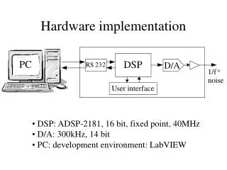
Hardware Implementation • This section shows the hardware implementation of the proposed parallel algorithm in terms of block diagrams. • The specification of the hardware design is: • Parallel Pixels to be inverse halftone= n= 15 • Number of SLUTs= 19
Two Blocks of hardware Implementation • The hardware system can be divided into two blocks: • RXC and modulus operators • 19pels to gray-level decoders
RXC and modulus operators • RXC and modulus operators components are responsible for the following tasks: Input: 19pels Output: SLUT numbers Slut • Accept 19pels from the halftone image and assign a sequence number to each entered 19pels. • Perform RXC operation on all 19pels. • Add the Slut value of the 19pels that has preceding sequence number to the current result. • Then take mod of the current result with a fixed number i.e. 19 in our case to obtain Slut value for the current 19pels. • The above three steps are pipelined so new 19pels are coming in while the current 19pels are in process.
RXC and modulus Block Diagram RXC calculation for 19pels Pn Pn-1 and Pn are two 19pels among all 19pels to be inverse halftoned in parallel. Slut is the Smaller LUT number where the concerned 19pels should go to fetch its inverse halftone value.
Hardware Design of RXC and modulus Operator • The next slides can show the hardware design of RXC operator for a 19pels pattern named Pn with the following parameters: • Parallel pixels to be inverse halftoned at a time= 15 • Total number of SLUTs= 19, therefore, Slut is from 0 to 19.
Comparison to halftone 256*256 Algorithm in [7] Proposed Algorithm Cycles/pixel 1 0.066 LUT size 5.1 K entries 19 K entries Latency 4 clock cycles 17 clock cycles Time taken 691.3502 ms 45.6389 ms
Conclusion and Future Work • A parallel implementation for inverse halftone has been presented. • Results can be improved by improving the operators and training. • Results obtained are encouraging.
Method to generate contents of SLUT • The algorithm is applied on images in a training set and Sluts values are obtained. • The 19pels then placed in the SLUT given by the corresponding Slut value.
Properties of SLUTs • The SLUTs were developed using training set composed of FS ED halftone images of Boat and Peppers of size 256x256-pixels. • The size of one SLUT is found to be 2.5K entries . • The summation of entries in all 19 SLUTs comes to be 42.6K. • The size of LUT in single LUT method is 9.86K entries, however, if the single LUT method is implemented multiple times for 15 parallel pixels the total size could become 148K entries. • In this way, our method can provide 3.5 times decrease in lookup table size over single LUT based method.
Behavior of RXC over Grey-level halftones Gray level 210 Gray level 130 NON Periodic Vibratory Response Periodic Vibratory Response Halftones obtained through Floyd & Steinberg Error Diffusion Method
Representation of RXC values on number line Periodic Vibratory Values RXC values to be used in SLUT access are calculated by adding the RXC to the RXC of the previous “19pels” That is: RXC for SLUT of Pn (Slut)= RXC of Pn-1 + RXC of Pn-2(n) From the number line we can see that adding RXC over previous values gives zero or constant result, therefore, we need NOT periodic vibratory response from RXC operator.