Download
1 / 10
100 likes | 162 Views
Volvo test plans. Euro I D-1 EN590 1500 ppm S D-4 EN590 8 ppm S D-5 Swedish Class 1 Stationary (ESC) Transient (ETC) Euro III D-2 EN590 300 ppm S D-4 EN590 8 ppm S D-5 Swedish Class 1 Stationary (ESC) Transient (ETC)

E N D
Volvo test plans • Euro I D-1 EN590 1500 ppm S D-4 EN590 8 ppm SD-5 Swedish Class 1 Stationary (ESC)Transient (ETC) • Euro III D-2 EN590 300 ppm S D-4 EN590 8 ppm SD-5 Swedish Class 1 Stationary (ESC)Transient (ETC) • Study the influence of CRT-based filter technology on particle emissions from an Euro III engine. Swedish Class 1 fuel (D-5) and two driving cycles (ESC and ETC) will be used. Fuel D-4 will also be tested if budget allows once the final sampling and testing protocol has been defined by WP-300.
Volvo test performed during 2002 Euro III D-2 EN590 300 ppm S D-4 EN590 8 ppm SD-5 Swedish Class 1 Stationary (ESC)Transient (ETC)Five steady states
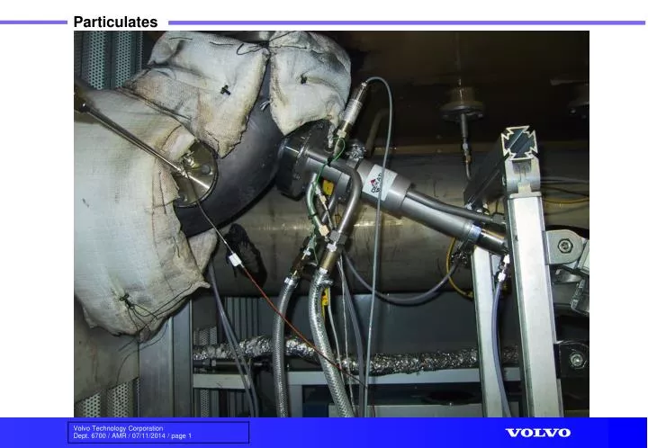
Problems and uncertainty factors. • Problem with primary dilutor – required modification as per Dekati drawing. • Water cooling of the primary diluter caused the temperature control to be difficult. • CPC required a very high dilution factor (11 250). • Pressure-spikes in the beginning of the measurement period due to air dryer. • 2 different ELPI’s were used – results do not correlate. • Dilution factor during SS points not stable – reduced as exh. temperature reduced.
Problem with fixing dilution factor: B • This was not initially noticed or known to be a problem. • In initial tests the primary dilution factor dropped to below 8. • A very long stabilization time was required to prevent this with subsequent testing. • As exhaust temperature drops, density increases causing a greater mass of gas to be drawn into the diluter since it is based on volume flows.