Download
1 / 22
220 likes | 384 Views
Mechanical Systems GLAST LAT Mass Properties Test Readiness Review. Contents. Test Plan Review Document List Objectives and Pass/Fail Criteria for the Testing Deviations from flight and configuration Test Configuration Pre-Test Analysis Calculation Tools Alignment and Accuracy Summary

E N D
Mechanical Systems GLAST LAT Mass Properties Test Readiness Review
Contents • Test Plan Review • Document List • Objectives and Pass/Fail Criteria for the Testing • Deviations from flight and configuration • Test Configuration • Pre-Test Analysis • Calculation Tools • Alignment and Accuracy • Summary • Test Procedure • Expected Test Durations • Personnel • Facility Readiness and Schedule • Action Item Form
Mechanical Systems GLAST LAT Mass Properties TRR: Test Plan Review
Mass Properties Test Plan – Objectives • The LAT will be set atop of a test platform where mass properties testing will be performed to accomplish the following objectives: • Measure the overall mass and CG of the fully integrated LAT • Verify the following three IRD requirements: • LAT mass does not exceed 3000kg • By Analysis, show Zcg is a maximum of 185mm above the LAT Interface Plane (LIP) • By Test, show X-cg and Y-cg are within 20mm of the LAT Coordinate System (LCS) Z-axis • A secondary goal is to verify that the measured mass properties coordinate with the math model mass matrix
Mass Properties Test Plan – Entrance/Exit Criteria • The Mass Properties Testing is performed following the LAT thermal vacuum test. The following criteria is to be met before the mass properties testing can begin: • LAT radiators have been removed and the LAT, flexures, and TIP have been moved into the mass properties test area- visual inspection verifies that all the LAT has been re-configured correctly. All travelers verified to be complete. The LAT is in its flight configuration, except as detailed in the test procedure and Slide 7. • Remove triple joint cover plate (non-flight) • Remove chiller bars • All subsystem units/modules function—each subsystem has passed its CPT following TVAC. Any performance discrepancies have been clearly documented. • Ensure all E-GSE cable harnesses have been removed from the LAT prior to test. • All load cells, support equipment, and electronics are in place and functioning properly. Instrumentation has been mounted in correct locations and orientations following the protocol in the test procedure. All non-fly-away accelerometers and other test instrumentation, cables and harnesses are removed or offloaded • Pass this Mass Properties Test TRR • Whether or not the mass properties testing is successful will be determined by the following exit criteria: • Visual inspection of the LAT verifying that there is no visual damage • Preliminary examination of the recorded data; all data is usable for analysis
Mass Properties Test Plan – Deviations From Flight • The following flight hardware is not installed for the mass properties test • Radiators not installed • Radiator Blankets • Fly away instrumentation shorting plugs • Miscellaneous tape and sealants • Additionally, the following non-flight items are installed • Connector savers • ESD/Contamination control Bag Remove LAT from test stand and move to mass properties plate Remove Radiators
Mass Properties Test – Test Configuration • The LAT is mounted to the test interface plate • The test interface plate is then lowered onto the test platform which will take the mass and cg measurements • The test platform comprises • An octagonal plate (LAT DS-08303) to transfer the weight of the LAT to the three load cells without inducing detrimental distortion to the TIP • Three load cells (5K Beowulf model 200-S P/N: LC2030 ) arranged in an equilateral triangle whose centroid is aligned with the LCS • NRL Modal survey plate which provides a stable platform for the test LC2 LC1 LC3 Test Platform Top View: Octagonal test plate and locations of the three load cells Test Configuration
Alignment and Accuracy • Alignment • To calculate mass and CG of the LAT, the load cell positions must be known w.r.t. the LAT coordinate system. To accomplish this, the following true positions are known: • Load cell positions w.r.t. indexing pin locations • Indexing hole and slot positions w.r.t. LAT coordinate system • From these positions, the load cell positions in LAT coordinate system is known. • From the Load cell positions, a sum of moments about the LCS is performed to calculate Xcg and Ycg • Accuracy • The 5 KIP load cells have been calibrated to be accurate within 0.5%, or ±25 lbf • A dry run was performed on 9/10/06 • 3000 lbf reference mass weighed in at 3007, 3012, 3011, and 3010 in four readings • Additional reference mass was added, which showed accuracy to 2.5 ± 0.5 lbf • Worst case aggregate error on mass is believed to be on the order of 10 lbf, or less than 0.5% • CG calculations will be taken in four orientations (0°, 90°, 180°, 270°) and then averaged in order to cancel round-off errors
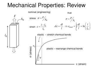
Mass Properties Test analysis - Summary • Mass properties platform has been analyzed to evaluate the following structural elements: • Distortion under load – peak distortion is 0.012 inches (minimal rotation) out of plane, which is on the same order of magnitude as plate flatness – under 1g load, this is insignifcant • Stresses in the plate – maximum stress under load is 2.54 ksi margins high • Tip-over loads – minimum lateral load for tip-over is over 1000 lbf, which is not credible • Handling loads – 2-point lift margins are high • Mass properties spreadsheet has been updated to include • 97.8% measured mass (2727.2 kg) • 2.2% calculated mass (61.8 kg) • Total mass = 2789.0 kg • Current Predictions (including radiators) • Xcg = -1.57 mm • Ycg = -1.2 mm • Zcg = -65.99 mm • Analysis is provided in the Back-up slides
Expected Test Schedule and Durations Date of Test: 9/12/06 – 9/13/06
Personnel The following personnel are responsible for the procedures of the test:
Mass Properties Facilities Readiness and Schedule • Facilities ready to go • Mass properties test dry-run complete on 9/10/06 all systems go • LAT ready to go • LAT extracted from TV chamber 9/10/06 • LAT rotation complete 9/10/06 • Radiator removal estimated completion 9/11/06 • LAT ready to test 9/12/06 – 9/13/06 • Preliminary report complete 9/14/06
Mass Properties TRR Action Item Form • Topic / presentation slide number: • Submitted by: • Actionee: • Request: • Reason / Comment:
Mechanical Systems GLAST LAT Mass Properties TRR: Back-up Slides
f Finite Element Models Shown below are the stress reactions (lbs/in^2) of the octagonal plate when the LAT and test interface plate are mounted on top and secured Shown above are the displacements (inches) of the octagonal plate when the LAT and test interface plate are mounted on top and secured
Finite Element Models Shown below are the displacements (inches) of the load cell base plate when a force strong enough to tip the load cell occurs Shown above are the stress concentrations (lb/in^2) of the load cell base plate when a force strong enough to tip the load cell occurs
Calculations Final Results of the Hand Calculations and Finite Element Modeling 1118 lbs Tip-Over Force for Load Cell 5010 lbs Tip-Over Force for Entire LAT ** The force for the load cell was calculated as if the force were applied at the top edge of the load cell, while the force for the entire LAT were calculated as if it were applied at the CG of the entire system **
Calculated Torques Required torques were calculated for three crucial fasteners in the mass properties testing • A tear out shear was calculated for the swivel rings • Calculated as a two-point lift • A36 steel has a yield of 36 ksi (21.6 ksi when the shear to tension yield ratio is considered) • The allowable shear would be 21.6 ksi, while the swivel had a tear out shear of only 7.9 ksi • The threat of a tear out is not realistic with the 1.5” plate
Drawings for the Load Cell Base and Octagonal Plate Shown below is the drawing for the octagonal plate Shown above is the drawing for the load cell base plate