Download
1 / 20
200 likes | 317 Views
Performance of the b-tagging algorithms with an upgraded CMS detector Eric Brownson Vanderbilt University (For the CMS Collaboration) DPF-APS Meeting, Aug. 9, 2011 Brown University, Providence, Rhode Island. Phase1 Tracker Upgrade.

E N D
Performance of the b-tagging algorithms with an upgraded CMS detector Eric Brownson Vanderbilt University (For the CMS Collaboration) DPF-APS Meeting, Aug. 9, 2011 Brown University, Providence, Rhode Island Meeting of the Division of Particles & Fields of APS, Aug 9, 2011
Phase1 Tracker Upgrade 4th Barrel layer, 3rd Forward disk, Altered cooling & electronics … • Restore current performance in PileUp scenarios above design luminosity • Redundancy to compensate for data loss • Take advantage of any other changes • Smaller beam pipe Must be backed up by studies Meeting of the Division of Particles & Fields of APS, Aug 9, 2011
3rd Disk & 4th Layer Different shape to the disks • Larger coverage in h Different spacing between the Barrel layers • Closer to IP & TIB Meeting of the Division of Particles & Fields of APS, Aug 9, 2011
Material Budget Barrel + Forward Forward only More sensors in more layers • In general move material out and away from IP • CO2 cooling • Lower the material budget Less interaction with the pixel tracker Current Geometry Phase1 Geometry Current Geometry Phase1 Geometry Rad length Rad length Meeting of the Division of Particles & Fields of APS, Aug 9, 2011
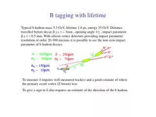
BDecay Products Flight Length ~ few mm Collision Decay Vertex Impact Parameter b-tagging Exploit the properties of b hadrons to distinguish b-jets from light (u,d,s,g) jets: • Large lifetime ~1.5 ps (large decay length: 20 GeV B-hadron decays after ~2 mm) • Search for tracks or vertexes displaced w.r.t. primary vertex • Large mass ~5 GeV • Search for leptons, from semileptonic b decays, with large transverse momentum w.r.t. jet axis Good tracking & Vertex reconstruction are needed Meeting of the Division of Particles & Fields of APS, Aug 9, 2011
b-tagging algorithm • Find jets in the Ecal & Hcal • Find High Quality Tracks with the Tracker • Calculate ImpactParameter • Match the Tracks to the jets • Build the discriminator Meeting of the Division of Particles & Fields of APS, Aug 9, 2011
Track Finding at High PileUp High Luminosity Read out inefficiencies & Fake Tracks ttbar events at 2x1034cm-2s-1, <PU>=50 @ 25ns High quality tracks similar to the requirements that are used in b-tagging http://home.fnal.gov/~cheung/tmp/plots4tp/TP_buildingPU50_btagtracks Meeting of the Division of Particles & Fields of APS, Aug 9, 2011
Vertexing Longitudinal Impact Parameter for all vertices • Improve with higher PT • Does best in central h regions • Phase1 Tracker provides improvement in vertexing Same story for the Transverse Impact Parameter… m–gun Sample Meeting of the Division of Particles & Fields of APS, Aug 9, 2011
Vertexing Transverse Impact Parameter for all Vertices • Slight improvement on Longitudinal • Phase1 provides most improvement for lower PT tracks The secondary vertices, together with other lifetime information obtained from the tracks you get … m–gun Sample Meeting of the Division of Particles & Fields of APS, Aug 9, 2011
b-tagging • CombinedSecondaryVertex tagger • Without PileUp the Phase1 tracker only provides gains w.r.t. the Current tracker • At 2E34 cm-2s-1 (2x Design Luminosity) the Phase1 shows some improvement on the Current tracker Meeting of the Division of Particles & Fields of APS, Aug 9, 2011
Restore Tracking at High PU High quality tracks similar to the requirements that are used in b-tagging ttbar events at PileUp=0 for Current Geometry & 2x1034cm-2s-1 for Phase1 Tracker Restore current tracking ability Meeting of the Division of Particles & Fields of APS, Aug 9, 2011
Restore b-Tagging at High PU Restore current performance at twice the design luminosity scenarios Open PileUp=0 for Current Geometry Filled 2x1034cm-2s-1 for Phase1 Tracker Meeting of the Division of Particles & Fields of APS, Aug 9, 2011
Conclusions • 2x design luminosity provides challenges for tracking • Increased fake track rates • Increased data loss • Reduced b-tagging • Plans are underway to compensate & restore our current level of performance • 4th Pixel Barrel Layer & 3rd Pixel Disk • Redundancy • Pixels both closer to and further from IP • Information from closer to IP & longer lever arms for fitting • Minimize material budget • Move as much as possible away from IP • More is under study • Better understand data loss, alter size & placement of pixels, develop algorithms for high PU and more… Meeting of the Division of Particles & Fields of APS, Aug 9, 2011
Backup Slides Meeting of the Division of Particles & Fields of APS, Aug 9, 2011
Reconstructed hits in the Phase1 Pixel Detector Meeting of the Division of Particles & Fields of APS, Aug 9, 2011
Current: Phase1 Tracker: Half disk consists of one inner blade assembly and one outer blade assembly and they are assembled next to each other View of the current Forward Pixel detector Meeting of the Division of Particles & Fields of APS, Aug 9, 2011
Data losses as a function of the L1 accept rate of the innermost layer of the current pixel detector. The instantaneous luminosity is 1E34 cm-2s -1 and the bunch spacing is 25 ns. CMS has been designed for maximum average L1 trigger rates of 100 kHz. The data points beyond this rate in the plot simply illustrate the linear nature of this data loss at this particular instantaneous luminosity with the PSI46v2 readout chip. Meeting of the Division of Particles & Fields of APS, Aug 9, 2011
Hit position resolution (RMS) as function of the track pseudorapidity for an unirradiated (blue lines) and irradiated detectors (red and green lines). Longitudinal (a) and transverse hit resolution (b) are shown separately. The solid lines correspond to hits with total charge Q below the average charge. Dashed lines correspond to hits with total charge 1 < Q/Qavg < 1.5. Meeting of the Division of Particles & Fields of APS, Aug 9, 2011
Effect of a 20% loss in efficiency of the TIB. The efficiency loss in track reconstruction is shown in (a) and (b) for low luminosities and 1E34 cm-2s-1. In (c) and (d), the ratios of efficiencies are shown. For the higher luminosities, this 20% loss in TIB efficiency would result in an overall relative reduction of 5% in the barrel region of the upgraded detector, but a 13% reduction in the current detector. Meeting of the Division of Particles & Fields of APS, Aug 9, 2011
Vertex Reconstruction • 1.0 ± 0.1 GeV/c (circles), 3.0 ± 0.2 GeV/c (squares) & 8.0 ± 1.0 GeV/c (triangles) • Filled and open symbols correspond to results from data and simulation • CMS PAS TRK 10-005 Meeting of the Division of Particles & Fields of APS, Aug 9, 2011