Download
1 / 28
280 likes | 385 Views
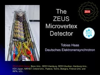
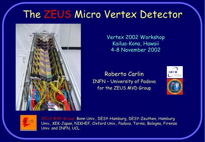
The ZEUS Micro Vertex Detector. Vertex 2002 Workshop Kailua-Kona, Hawaii 4-8 November 2002. Roberto Carlin INFN – University of Padova for the ZEUS MVD Group.

E N D
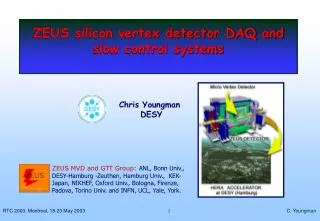
The ZEUS Micro Vertex Detector Vertex 2002 Workshop Kailua-Kona, Hawaii 4-8 November 2002 Roberto Carlin INFN – University of Padova for the ZEUS MVD Group ZEUS MVD Group:Bonn Univ., DESY-Hamburg, DESY-Zeuthen, Hamburg Univ., KEK-Japan, NIKHEF, Oxford Univ., Padova, Torino, Bologna, Firenze Univ. and INFN, UCL.
This is what we were expecting last • year, but things went differently: • Hera startup difficult with very high radiation backgrounds • A short lumi run is starting in November, we will need a 3 months shutdown (spring ?) to get things really under control • Outlook: • The structure of Zeus MVD • Status of MVD, dead channels and some reason for that • Cosmic rays runs and alignment • Backgrounds, noise in the detector • First measurements with e-p events • Irradiation of MVD and how to cope with it
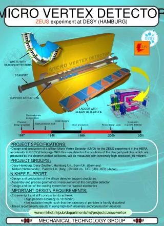
120 mm • Readout with analogue chip (HELIX3.0, Heidelberg+Nikhef) built with AMS 0.8 CMOS technology • Only preamp, analog pipeline and drivers on chip • LVDS Clock and Control drivers 6m far on special patch boxes • ADCs 30m far on the MVD racks ! • Special care on cabling, signal handling, grounding, shielding… Si detectors and FE readout • n-doped silicon wafers (300 m thickness) with p+ implantations (12 or 14 m wide), HAMAMATSU PH. K.K. • 512 readout AC coupled channels in the barrel, 480 in the wheels • Using the capacitive charge sharing, the analogue readout of one strip every 6 allows a good resolution (<20 m) despite the readout pitch of 120 m
125 mm 64 mm • Two single side sensors are glued and bonded to gold strips plated on Upilex flex foils, and finally to a FE hybrid • Two planes are glued together to form a module with x-y readout • Five modules are mounted on a carbon fiber support structure to form a ladder. • The Si planes, Hybrids and Cabling are located on the 3 planes of the ladder • 30 ladders, in 3 planes, are positioned around the elliptical beam pipe in the MVD barrel detector Modules in the BARREL
Same electronics and connectivity as in the barrel And in the forward WHEELS • The forward wheels have detector differently shaped (trapezoidal with two different sizes to accommodate the beam pipe) • Two layers of single side Si detectors, same pitch and construction as in the barrel, strips cross at an angle of 26°
All cables in a Faraday cage • The barrel section: • 30 ladders • each one composed of 5 modules of 4 Si detectors • Total of 300 hybrids, >150k channels • The forward section: • 4 wheels • each one composed by 2 layers of 14 Si detectors • Total of 112 hybrids, >50k channels • The read section: • Cooling pipes and manifolds • Distribution of FE, slow control and alignment cables Overall structure and inventory One half of the entire MVD
Noise in ADC counts for each strip in the barrel (one histogram per ladder) Status of the MVD: limited number of bad channels in the barrel Old Dead Modules “Fixed” Modules (optimizing HELIX programming): Modules noisy sometimes or partially (to be investigated) New “Noisy” Modules
And much less in the wheels • No problematic module in the wheels. Why? • Factor 3 less channels • In the barrel there may be one problem in the cabling • details • Characteristic noise structure: • In the wheels the strips have different lengths • Different input C to the FE chips, different noise
Ladder cabling Hybrids Cables Si planes • Very tight cabling • Use one side of the ladder for cabling • Use special, very thin custom cables • Minimize use of components and connectors
Connect the hybrids via flex circuits on miniature ZIF connectors Connectors to daisy chain the hybrids Termination resistors and filter capacitors Special custom multifunction (“combo”) cable Connectors to provide LV, HV, control signals and extract analog output 500 m pitch flex connection, pre-bent
Vias between circuits and to soldering pads Flex layer with stiffening to match the ZIF connector glue G10 circuit layers • Many more problems than expected: • Very hard to cut the flex PCB with enough precision (50 m) to fit the 4 ZIFs in the 2 hybrids. Relative positions were important! • Not easy to get the circuit of the proper thickness for the ZIF insertion (300 m) • The conductors in the vias do not adhere to the glue, it makes a bridge between the layers (point of fragility) • The glue is hygroscopic ! • When soldering close to vias, the T increase may create vapor that break the conductor in the via (and in extreme cases delaminate the connector) • Solutions: • Slow drying of PCBs in oven, and then store in vacuum bags • Controlled soldering operation • Extensive test of PCBs and of cabling at the company • Test with (relatively) high currents at the lab • Nevertheless, some of the dead module show bad connectivity at the PCB
On the wheels there is more space for • cabling • Standard PCB to connect cables and put components • Bridge between PCB and hybrids with flex jumpers, ZIFs on both sides • Installation at the end turned out to be “easy” • No connectivity problem sofar on the wheels • NB extra ZIFs would not have fit in the barrel
Use the two semi-tracks as they were independent, to measure the resolution in impact parameter • 117 um resolution, without alignment (p<1Gev tracks) MVD is working fine, test tracking with cosmics
First alignments with cosmics • Alignment code is being developed and was tested on a sample of cosmics • The results show that the module positions in each ladder are well known • Very precise construction, markers aligned under microscope (10um) • Very rigid ladder structure • First iteration will need only ladder alignment (factor 5 reduction in free parameters) • Need lot of good tracks (400K), corresponds to 2pb-1, feasible in the coming winter run despite of the bad background conditions • A laser alignment system is present and will monitor overall rigidity Alignment of each module Module are fixed in the ladder, ladders only are aligned
Data taken is dominated by background • High detector occupancy with bad • background data • Question: • Is it all background, or is there a contribution from noise? • Do we have any pick-up, coherent noise? Occupancy from e-p (DIS) events
Clustering (performed by the ADC) • A threshold is applied to each strip • Independent for each strip, usually set to 3 noise • A cluster is a set of consecutive strips above threshold (a single hole is allowed) • The two “side strips” are part of the cluster • A further cluster sum threshold can be applied • The cluster size on pedestal events is consistent with a stochastic distribution of noise in the strips • The noise hit distribution is consistent with a stochastic 3 noise in the strips • A noise cluster is composed by 3 strips (one above threshold) • The number of noise hits should be 0.15% per channel per event if the threshold is set to 3 noise • Thresholds are a little lower than 3 (truncation to integer ADC counts) Detailed studies of noise
Cluster sums show clear Landau • distribution • On average a little smaller than in the system test with cosmics • S/N 14 instead of 16 • Likely reason: sampling a little off-time (signal rise time<40ns) Good events are clearly seen in the MVD
dE/dx looks OK Using the cluster charge, corrected for path length in Si, we get a nice dE/dx distribution from good e-p events
16 Si PIN diodes (8 modules) with DC (current) readout to generate alarms and beam dumps (and tune beams) • Integrating currents: • No threshold for any background (Synchrotron light) • Need treatment of leakage current • Use an “leaky bucket” logic (a la Babar) to dump beams • Plan to use empty bunches to measure the leakage currents (1.2 s available) • 8 radfets to have a continuous monitor of the integrated dose • Readout every 15 minutes • Very valuable to assess the overall quality of HERA operations • TLDs exchanged monthly to cross-check the results from radfets We got some irradiation, but we monitor it properly
Total dose received ? • Results from rear RADFETS in the last months of operations • One module is at 80 Krad. This is located close to a collimator and sees the showers from low momentum leptons hitting it • The other (also in the forward) measure doses within 20 Krad • Doses in MVD between 20 and 80 Krad, in the most affected areas (inner layer, inside HERA ring) • MVD irradiation mostly with chips OFF • Beam losses at injection or ramp-up (mostly e beam) • Bad e-beam injection • Sensitivity reduced a factor 2 or more • Only marginally from normal operations (but currents were limited sofar)
S/N ratio measured with chips connected to a single Si detector (input C= ½ w.r.t the actual barrel readout) Noise increase measured at Heidelberg with 0 input C Radiation Tolerance of MVD • The most sensitive component is the HELIX chip • AMS 0.8 CMOS technology • Designed to be radiation tolerant • Tested by Heidelberg (for Hera-B) and by Nikhef (for ZEUS) • Fast decrease of S/N ratio for the first 100 Krad • Change of shaping time and other parameters • Helix has programmable parameters (internal DACs) to recover the working points • 5 Krad/yr expected from beam operations (up to 100 Krad inside on bending plane, low p leptons) • ZEUS has set a maximum radiation budget of 300Krad in the lifetime of the detector
Study of signal shape using HELIX internal test pulse (time scans) • No evidence of gain variations with time • No evidence of peak time changes Stability of the HELIX working point
Stability of the HELIX working point • Only sign of irradiation in the chips • Limited increase in the noise for the inner layer of the BARREL (1.5%) Noise (ADC counts) Day of the year
Change of gain with Ipre, for diffrerent irradiations • Signal decreases • Can be recovered, at least partially, with a higher Ipre current • There is space in the cooling and LV power supplies for extra power to the chips • Change of peak time • Signal becomes faster with irradiation • Increase of Ipre make it even faster • Need to recover with shaping time
Changes with Vfs • Peaktime can be recovered • At the same time also the S/N recovers
Summary • MVD commissioning limited by backgrounds in HERA • Number of non-working channels small after one year from the beam startup • The noise distributions are under control • Data from cosmics and first events look promising, tuning needed • Alignment underway, need much more data. The detector is well measured and rigid • 20-80 Krad collected, but sofar no clear evidence of damage • “Luminosity run foreseen November ...”
Side strips must be sampling a noise distribution on a random noise hit • Again, no coherent noise or cross-talk • On BG (or physics events) they must carry some induced charge information • OK, included in the cluster Thresold cut Detailed studies of noise (2)