Download
1 / 27
280 likes | 448 Views
NUMERICAL SIMULATION OF SOLID STATE AMPLIFIER INCORPORATING AMPLIFIED SPONTANEOUS EMISSION. GJ Van der Westhuizen , JP Burger, EG Rohwer, JN Maran Laser Research Institute, Department of Physics, University of Stellenbosch, South Africa. Introduction Aim of project Numerical model

E N D
NUMERICAL SIMULATION OF SOLID STATE AMPLIFIER INCORPORATING AMPLIFIED SPONTANEOUS EMISSION GJ Van der Westhuizen, JP Burger, EG Rohwer, JN Maran Laser Research Institute, Department of Physics, University of Stellenbosch, South Africa
Introduction Aim of project Numerical model Theoretical predictions Sensibility check of numerical predictions Experimental design Comparison Discussion Summary Outline
Fibre lasers have a number of advantages over conventional solid state (SS) lasers: Excellent beam quality Compact No external cooling required High mechanical stability and low thermal load (Large surface-to-volume ratio) Introduction • Solid state (SS) laser materials have a larger energy storage capacity
Developing a laser system in pulsed regime for dental and industrial applications with: Good beam quality Pulselength ~ 1ps Energy ~ 1mJ Repetition rate: from 1 to 10 kHz Materials choice: Yb:glass fibre laser oscillator Yb:YAG SS amplification stage Aim of project
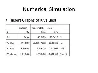
We wish to obtain: Small signal gain extractable from crystal Influence of Amplified spontaneous emission (ASE) at high gain Energy storage capacity of crystal Recently used existing equipment to check if the numerical simulation gives sensible results Topic of discussion Developed numerical tool capable of simulating behaviour inside SS amplification medium for designing amplifier stage
Assumptions used in calculations Steady state conditions Very fast non radiative transitions between energy levels other than lasing transition Uniform intensity distribution of pump light (diode) inside crystal (i.e. top hat distribution) Top hat minimizes beam distortion due to non-uniform transversal gain distribution (non-saturating) Energy extraction goes down compared to Gaussian pump profile?? Want to retain M2-value of input beam ASE spectrum has Lorentzian lineshape Numerical Model
Numerical simulation based on rate equation formalism We first consider: Use Gaussian beam width: Power Gain Geometrical Gain
Propagation equations: σ = Absorption / Emission cross section F = Geometrical focus terms S = Spontaneous emission term
Simulation algorithm Divide gain crystal into segments along optical axis Assume n2 to be zero in each segment Process is repeated until numerical Steady State is reached Numerically integrate using Runga-Kutta: Ip(n2) , Is(n2) Numerically integrate using Runga –Kutta: Ip(n2), Is(n2) and IASE(n2) Calc new n2(Ip,Is) in each segment ASE is resolved in 100 different λ’s
Design of experimental setup: Pump light provided by multimode fibre coupled diode Multimode fibre yields top hat intensity distribution (measured M2 = 314) Use Gaussian optics to design beamtrain for pump Use second moment to calculate the Gaussian distribution equivalent to top hat: Sensibility check of numerical predictions
Trivially find that , since according to the second-moment based beam width definition Can now design beamtrain for embedded Gaussian beam, where: Complex amplitude of optical field given by: Beamtrain obtained by transforming complex q-parameter by relevant ABCD matrices Multiply all half-widths in beamtrain by M
Experimental Setup: Diode PB WP L3 L1 L2 M1 Nd:YAG Laser Nd:YVO4
Top hat profile predicted by GLAD and physical optics calculations: Roughly 60% of pump power under top hat in waist (ω = 200μm).
Choose a waist of ±60μm for Signal (Nd:YAG, M2 = 1.14) at front surface of crystal (D ~ 3W)
Pump dependence of gain Comparison
Small gain → ASE not significant Some discrepancy between model and experiment Reason: Pump profile distorted by spherical aberrations Aberrations expected with spherical lenses used at low effective f-numbers (1.5 – 2.0) Measured M2 –values for pump light after lenses are double that of light emitted by multimode fibre We cannot model complex beam behavior (propagation position dependent beam profile and detailed transverse position dependent saturation) Discussion
At waist z = 0 mm In front of waist z = -1 mm Measured beam profiles z = +1 mm Behind waist Behind waist z = +2 mm
Small gain in this experiment applicable to regenerative amplifier We will probably try to achieve higher gain ~10dB (for two-stage double pass amplification) Use Gradium™/ aspheric lenses for pump in Yb:YAG amplifier to minimize aberrations For Yb:YAG double-pass amplifier is preferred: Simplified experimental setup Less active switching by means of Pockels’s cells (compared to regenerative type of amplifiers/systems) Discussion (continued..)
Numerically simulated behavior inside crystal incorporating focusing effects, ASE, propagation coordinate dependent inversion (up-conversion can be added in future if needed) Designed experimental setup yielding top hat at crystal waist (for comparison) Set up experiment, and characterized the actual pump beam Obtained experimental results that shows model gives sensible numbers Software can easily be modified to model pulse amplification Summary
Want to Thank: • Dr. Burger and Dr. Maran • You all for listening