Download
1 / 47
530 likes | 830 Views
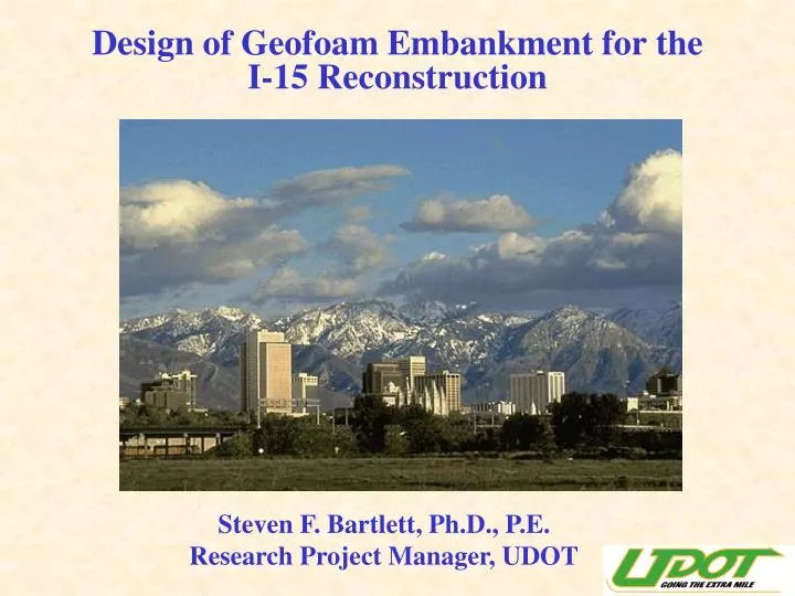
Design of Geofoam Embankment for the I-15 Reconstruction. Steven F. Bartlett, Ph.D., P.E. Research Project Manager, UDOT. I-15 Reconstruction - Quick Facts. Single Largest Highway Contract in U.S. 17 Miles of Urban Interstate $1.5 Billion Design-Build

E N D
Design of Geofoam Embankment for theI-15 Reconstruction Steven F. Bartlett, Ph.D., P.E. Research Project Manager, UDOT
I-15 Reconstruction - Quick Facts • Single Largest Highway Contract in U.S. • 17 Miles of Urban Interstate • $1.5 Billion Design-Build • 4 Year Construction Duration (Summer 2001) • 144 Bridges/Overpass Structures • 160 Retaining Walls (mostly MSE Walls) • 3.8 Million m3 of Embankment Fill • 100,000 m3 Geofoam Embankment
Primary Uses of Geofoam on the I-15 Project • Reduce Settlement to Protect Buried Utilities • Improve Slope Stability of Embankments • Rapid Construction in Time Critical Areas
Settlement Reduction (continued)Subsurface Profile in Salt Lake Valley Alluvium Bonneville Clay Soft Clay (10-m thick) Pleistocene Alluvium Cutler Clay
Settlement Reduction (continued)Settlement on I-15, Salt Lake City (1964 - 1968) 11.6 m Fill Height 2.5 year duration 1.4 m Settlement Primary Settlement
Buried Pipeline NEW FILL Buried Pipeline Ruptured Pipeline Settlement Reduction (continued)Buried Utilities
Settlement Reduction (continued)Buried Utilities along Roadway Buried Utilities Geofoam Embankment from State St. to 200 W. Along Interstate I-80, Salt Lake City, Utah
Improve Slope Stability (continued)Diagram of Potential Instability at Bridges cracks Bridge Deck Failure surface Soft Clay
Improve Slope Stability Details of Geofoam Construction at Bridge Abutments
GEOTEXTILE Rapid Construction(Typical Embankment Construction for I-15)
Rapid Construction(Typical Embankment Construction for I-15) Wick Drain Installation (4 weeks) Grading and Geotextile (4 weeks)) Wall Construction + Settlement Time (6 weeks + 24 weeks) Concrete Panel Placement (2 weeks)
35 cm Concrete Pavement 60 cm Base Material Tilt-up Concrete Fascia Panel Wall Geofoam Block Sloped Embankment (1.5 H to 1 V max.) Wall Footing Bedding Sand (20 cm min.) Rapid Construction(Typical Geofoam Construction for I-15) 15 cm Reinforced Concrete Load Distribution Slab
Rapid Construction(Typical Geofoam Construction for I-15) Block Placement (3 weeks)) Grade Preparation (1 week) Load Distribution Slab Construction (2 weeks) Panel Wall Construction (1 Week)
Rapid Construction(Comparison of Construction Time) Construction Time (Weeks)
Design Considerations • Material Type • Dimensions • Density • Compressive Strength • Allowable Load & Creep • Interface Friction • Stability of Internal Slope • Bedding Material & Compaction • Concentrated Loads • Moisture Absorption • Buoyancy • Thermal Resistance • Differential Icing • Chemical Attack • Flammability • Insect Infestation • Ultra Violet Degradation • Durability
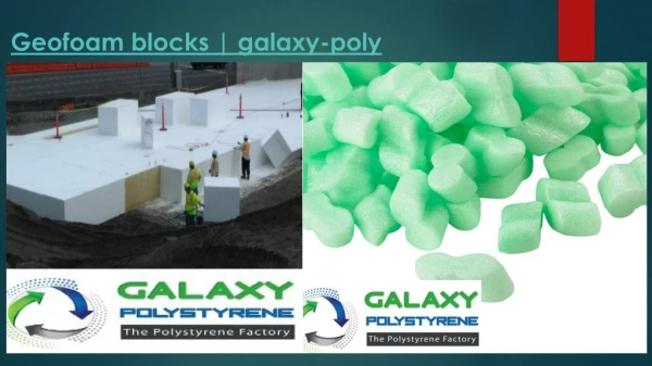
Design Considerations(Material Type) • Expanded Polystrene (EPS)* • virgin feedstock • maximum of 5 percent regrind content * Extruded Polystrene (XPS) is also available, but was not used on the I-15 project
81 cm 488 cm 122 cm Design Considerations(EPS Block Dimensions) • Dimension tolerance 0.5 percent • If tolerance is met, no trimming is necessary • If tolerance is not met, shop trimming is necessary
Design Considerations(EPS Density) * Type VIII was used for I-15 Reconstruction
Design Considerations(EPS Minimum Compressive Strength) * Type VIII was used for I-15 Reconstruction Strain Rate for Testing = 5 mm / minute
Design Considerations(EPS Minimum Compressive Strength Versus Density) (Source: Bartlett et al. 2000) sd = 7.3 * D - 47 where D = Density in kPa.
Design Considerations(Allowable Stress and Creep) Source: Negussey (1997) Type VIII EPS sd = stress @ 5% strain 0.4 sd Simplified Formula: Allowable Stress = 0.4 sd Allowable Stress = 0.4 x 120 = 48 kPa * Allowable Stress Must Maintained Below 1% Axial Strain to Minimize Long-Term Creep
Design Considerations(Allowable Stress and Creep) Allowable Stress (Dead Load + Live Load) < 0.4 sd Dead Load = Weight of Load Distribution Slab + Weight of Base Material + Weight of Pavement. Dead Load = 30 % of sd = 0.3 sd Live Load = Traffic Loads Live Load = 10 % of sd = 0.1 sd
Design Considerations(Creep Data from Norway) Measured Data (3.5 years) Theoretical Model (Source: Aaboe, 2000)
Theoretical Model (Source: Aaboe, 2000) Design Considerations(Creep Data from Norway)
sn EPS BLOCK Lateral Force t • Interface Friction Need for Design Against Sliding • t = sn tan f • t = sliding shear resistance • sn = normal stress • tan f = 0.6 (Design Value) • f = 31 degrees (Design Value) Design Considerations(Interface Friction)
Design Considerations(Interface Friction) Design Value = 31 deg. Source: Negussey (1997)
Design Considerations(Stability of Internally Sloped Embankments) Back Slope 1.0 Vertical Force = 0 1.5 Horizontal (Do Not Allow Transfer of Horizontal Force) Maximum Back Slope = 1.5 H to 1.0 Vertical for Embankment to Guarantee Internal Slope Stability
Design Considerations(Stability of Internally SlopedCuts and Hillsides) Reinforced Slope Soil Nails, Soil Anchors, or Other Reinforcement Cut Slope or Landslide
Bedding Sand (20 cm min.) Design Considerations(Bedding Material and Compaction) • Bedding Sand Function • free draining sand or fine gravel • provides leveling course • provides drainage
Design Considerations(Bedding Material and Compaction) Gradation Specification for Bedding Sand Sieve Size 50mm13mm6mm2mm0.425mm0.075 mm % Passing 95 - 100 65-100 50-100 40-70 10-40 0-5 (Percent Passing) * Materials with more than 20 percent of the samples containing between5 and 7 percent minus 0.075 mm material shall not be accepted for use.
Design Considerations(Bedding Material and Compaction) Light-Weight Compaction Equipment Grade Preparation and Leveling (*Maximum lift thickness = 20 cm)
Design Considerations(Concentrated Loads) • Uncovered geofoam damages easily from tire loads • Do not use heavy equipment atop geofoam • until the load distribution slab is placed • Use light-weight construction equipment • Protect with plywood sheeting
Design Considerations(Moisture Absorption - Above High Groundwater Elevation) (Source: Aaboe, 2000)
Design Considerations(Moisture Absorption - Below Groundwater) (Source: Aaboe, 2000)
Design Considerations(Moisture Absorption - Design Values) • Installation of EPS above high groundwater • Design Moisture Content = 1 percent by volume • Installation of EPS that is periodically submerged • Design Moisture Content = 5 percent by volume • Installation of EPS below groundwater • Design Moisture Content = 10 percent by volume
Design Considerations(Buoyancy) Fresisting 100-year design flood event groundwater Fuplift Drainage Sand Fresisting = 1.3 x Fuplift
Design Considerations(Thermal Resistance) (Negussey, 1997) • R-value = heat flow through a unit width of material. • R-value for geofoam is about 4 (18 kg/m3 density). • R-value for soil and concrete is less than 1.
Icing EPS Poor Heat Transfer 60 mm base (min.) Design Considerations(Differential Icing - Cold Regions only) No Icing pavement soil Good Heat Transfer No Icing Base material has heat capacity and prevents pavement from icing as rapidly. Proper Design to Prevent Icing
Design Considerations(Chemical Attack) • Solvents that Dissolve Geofoam • Gasoline • Diesel • Other Petroleum Based Fuels • Organic Fluids • Protection Against Accidental Spills • Concrete Load Distribution Slab • Geomembrane • Fascia Panel Wall with Coping
Design Considerations(Chemical Attack - Protective Barriers) Concrete Pavement (35 cm) Load Distribution Slab (15 cm - Reinforced) Geomembrane Petroleum Resistant (3 component) for exposed side slope only Tilt-up Panel Wall
Design Considerations(Chemical Attack - Protective Barriers) • Tripolymer Geomembrane • Polyvinyl Chloride • Ethylene Interpolymer Alloy • Polyurethane • 9 mm thickness minimum (total)
Design Considerations(Flammability) • Geofoam is Combustible and Must Be Protect Against • Open Flame or Heat • Material Specification should include: • “Flame Retardant Additive and a UL Certification of • Classification as to External Fire Exposure and • Surface Burning Characteristics.”
Design Considerations(Insect Infestation) • Chemical (Borate) can be added to stop termite • or insect infestation.
Design Considerations(UV Degradation) (Bartlett et al., 2000) Prolonged Exposure ( > 90 days) to sunlight can lead to discoloration of geofoam and decrease in the internal angle of friction on the surface of the geofoam.
Design Considerations(UV Degradation) • Geofoam should not be left uncovered more than 90 days. • UV exposure times greater than 90 days require • “power-washing” to remove degraded geofoam surface • where the load distribution slab is placed • Side surface where tilt-up panel wall is placed do not • require power-washing.
Design Considerations(Durability Data from Norway) Note: No loss of compressive strength with time is evident (Source: Aaboe, 2000).