Download
1 / 12
120 likes | 195 Views
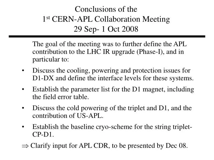
Conclusions of the 1 st CERN-APL Collaboration Meeting 29 Sep- 1 Oct 2008. The goal of the meeting was to further define the APL contribution to the LHC IR upgrade (Phase-I), and in particular to:

E N D
Conclusions of the 1st CERN-APL Collaboration Meeting29 Sep- 1 Oct 2008 The goal of the meeting was to further define the APL contribution to the LHC IR upgrade (Phase-I), and in particular to: • Discuss the cooling, powering and protection issues for D1-DX and define the interface levels for these systems. • Establish the parameter list for the D1 magnet, including the field error table. • Discuss the cold powering of the triplet and D1, and the contribution of US-APL. • Establish the baseline cryo-scheme for the string triplet-CP-D1. Clarify input for APL CDR, to be presented by Dec 08.
Input information Peter DX and D1 Amalia Cold powering and MgB2 bus Tommy Crogenic scheme Sandor Nb-Ti bus Mike Al- bus Paolo Internal busbars Considerable contribution from all participants in an open and constructive atmosphere.
D1 Service module (includes SC junction box) Correctors Quads SC link Current leads Warm helium from leads Jumper connections From the DFBX-E Flow schematic QRL
D1 magnet • The D1 cold mass will contain two LDX magnets placed back to back. The cold mass will have a common helium vessel. • The coil and cable design of the LDX magnet will be identical to the RHIC DX beam separation dipole. There will be no change in the design of end-spacers and other coil components, nor in the target coil pre-compression. • The baseline yoke shape will be oblate. The details of the yoke will be designed to optimize the field errors, and the mechanical and electrical features of the magnet. • D1 will be designed and delivered as a “stand-alone” magnet with a warm bore, adaptable to the tunnel slope with no (or minimal) modifications. CERN will provide and install the beam tube. • The baseline protection scheme of D1 will be similar to that of the Phase 1 upgrade quadrupoles, using energy extraction and quench heaters. The implementation of the scheme will depend on the result of tunnel integration studies, which will be completed before December 2008.
D1 magnet • Magnet specific instrumentation (voltage taps, quench heater leads, temperature sensors, level gauges, et cetera) will be brought out locally from the magnet cryostat using an IFS interface unit supplied by CERN. • CERN will supply the cabling, detection electronics and quench power supplies for tunnel installation. • The magnet will contain the necessary voltage taps for busbar protection, to be routed with the busses. • Redundant level sensors will be installed inside the cold mass, on both sides. • The D1 magnet will be run at 4.5K with liquid bath cooling. BNL and CERN will jointly adjust the features of the yoke to match this scheme. • CERN will provide temperature sensors and BNL will provide level gauges.
D1 magnet • Main parameters: • Temperature 4.5 K (liquid bath cooling) • Redundant level sensors inside the cold mass (both sides) • Current: • Nominal 5.6 kA (27 Tm) • Top 6.5 kA (80% Iss) • To be trained up to 7.5 kA (RHIC test programme) • Nominal ramp rate 5 A/s (up to 18 A/s given by the PS) • Field errors: • Ver 1.0 error table to be supplied by BNL on the basis of DX warm and cold measurements, including avg, min/max, for nominal and injection currents (Rref =40 mm). • The yoke should be optimized for a b3 error of ~1 u (Rref=40 mm), with attention to b3 at injection. • The source of a2 should be identified, and reduced to a level of 1 u (in the new cryostat).
Cold power transfer system The cold power transfer system consists of the following items, as shown in the block diagram of Figure 1: • Current lead box (DFX), providing the cold-to-warm electrical power connection between the Superconducting Link and warm cables carrying the current to and from the Power Converters. • Superconducting Link, carrying the magnet currents over some 10's of meters from the DFX and the power converters, which are placed out of the tunnel in an underground service area. • Superconducting Junction Box, which provides the interface between the Superconducting Link and a Service Module. • The Service Module, which provides the final interface between the cryogenic and electrical systems, and the triplet magnets. The Service Module might contain the Junction Box itself. The design of the current leads, DFX, and SC link will be performed by Fermilab as part of the joint TDR. FNAL and CERN will collaborate on the interface design. CERN will assign an engineer to closely follow this work. The construction and delivery of the DFX and SC link will be the responsibility of Fermilab.
Superconducting link • The baseline design is for a single superconducting link cryostat housing the links from the D1, correctors and the inner triplet quadrupoles. • For the inner triplet, there will be 4 high current superconducting links cables rated for 13 kA, and two links rated for 2 kA. For D1 there will be two links rated for 7kA. Correctors will require 4 links rated for 2.5 kA for a high current orbit correctors, and up to 8 additional links rated for 0.6 kA. • Rather than develop a bus for each power requirement, APL and CERN will also see if it is practical to service all magnets with only a low current (0.6kA) and high current bus (13 kA). • Depending on the final quench protection scheme, voltage taps may be routed along the SC link, to be read out through the DFX. • The SC link will have an OD of approximately 200 mm and a minimum bending radius of 2 m. The routing of the link will depend on the tunnel details. The link is expected to be about 20 m long in IP1 and 60 m in IP5. The details of the routing will be available by the end of December 2008. • APL will assume a baseline link implementation using NbTi bus cable. The type of cable will be decided by APL before the release of the CDR, according to the existing experience and strand availability. It might be possible to combine link and D1 strand purchases. • APL and CERN will investigate the possibility of using the same bus cable for the internal busbars in the quadrupoles.
Superconducting link • CERN R&D for a link based on MgB2 cable (for which CERN has a long term interest) is largely decoupled from the design of the most costly elements of the cold powering (DFX, link cryostat, tunnel connection box). CERN R&D on MgB2 will proceed independently of APL through the end of 2009. • The decision on whether to use the NbTi bus cable, or a CERN supplied MgB2 cable, will be made towards the end of 2009. The link, DFX, and current lead designs will be made compatible, as far as possible, with either type of cable. Differences or branch points in design which depend on cable type will be noted. • The baseline cooling scheme for the link is based on returning a small fraction of 3 bar, 4.6 K supply for the leads through the link shield and back to the 20 K line, independent of the type of cable used in the link. A re-cooler for the He coming from the 4.5K QRL header will be considered to guarantee the input temperature to the link.
Current lead box, Service module and SC junction box • The current lead box (DFX) will have an OD of approximately 1 m and a length of approximately 3 m. • The available cryo-headers and controls at the level of the QRL jumpers are well matched to the requirements of the new triplet+D1 in 5L with minimal changes. This will be checked for the other three triplets. • A shift of the service module by one or two QRL-pipe sections may be the most effective solution for providing the QRL interface. CERN will define the solution by the end of 2008. • APL will examine the possibility of designing and delivering a service module. The service module for the triplet will be housed preferably between D1 and CP, and will combine the bus junctions and cryogen supplies to the 1.9 K system (CP+triplet), the 4.5 K system (D1) and the link.
Misc. • Attention is brought to the design of the GPI, beam tube insulation and collar packing to minimize obstruction of the heat path from the heat source (first coil layer) to the internal HX. • A He collector pot could be placed in the Q1-Q2 interconnect, attached to a transfer 16 mbar pipe, necessary in all magnets. This is an alternative to a design where the pot is located at the IP end of Q1.