Download
1 / 12
120 likes | 232 Views
Mainz hardware activities - c lock module for TB spring 2012 - . R.Degele , P.Kiese,U.Schäfer , A.Welker Mainz. CCC. Current status: UK-developed CCC exists and is being used for clock distribution in beam tests and in the lab M ature design, based on CPLD and discrete fan-out / drivers

E N D
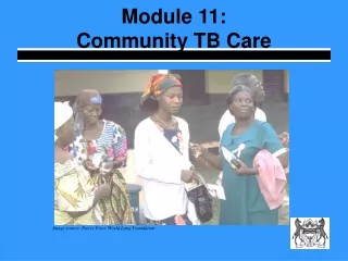
Mainz hardware activities- clock module for TB spring 2012 - R.Degele, P.Kiese,U.Schäfer, A.Welker Mainz
CCC Current status: • UK-developed CCC exists and is being used for clock distribution in beam tests and in the lab • Mature design, based on CPLD and discrete fan-out / drivers • Jitter specs seem rather unclear • CPLD seems rather full • Not designed for future use Calice integration with EUDET / AIDA TLU / beam telescope (Disclaimer: That’s my personal level of (mis-)understanding) • CCC situation has been discussed at CALICE & AIDA mini workshop (Nov.2011, Palaiseau) Provide improved/extended module at a timescale spring 2011 (beam test), addressing main issues. Scope for further improvements thereafter.
Some preferences / issues As of Nov.2011 (Palaiseau) for future electronics we would consider: • FPGA based modules • Custom designs make use of FMC standard (mezzanine modules) • Think about crate based modules rather than table-top (VME-6U?) • For readout and control consider Ethernet (direct FPGA-based, not micro controller(core)) Medium term (common test beams): Remember need for integration of Calice clock modules with EUDET/AIDA TLU • Discussions with D. Cussans (Bristol) : Common hardware development Calice clock module / mini TLU • TLU distributing synchronous triggers,Calice (CCC) triggers are asynchronous signals !!!
TLU integration Sketch by D. Cussans: Combining TLU and BIF
Something to think about (for the experts) • It has been suggested to go for FPGA based modules • Asynchronous code in FPGAs is horrible. • TLU is operating on synchronous signals for exactly that reason Can we operate Calice detectors/electronics on synchronous triggers ? • Measure phase of all incoming signals on machine interface (scintillators, test beam signals,…) wrt to global clock (TDC) • Issue synchronized (to global clock) trigger signals to LDAs detectors • Send TDC data into DAQ for offline corrections Questions: • What’s acceptable trigger jitter if not using offline correction ? • What’s required resolution of TDC if using offline correction ?
Quick fix TB spring 2012 • Build a rather dumb module (connectors, drivers/level translators) to be plugged on Xilinx ML605 evaluation board (FMC) • Route all signals through FPGA • Control jitter and skew to required levels (???) • Replicate CCC functionality • Integrate TLU functionality for connection to beam telescope • In case it turns out later that we do require asynchronous operation, bite the bullet and do that horrible code Your input is required: • In case there were a strong bias against synchronous triggers we’d rather know now. Might have to go for quite different scheme • Need to verify need for replication of full CCC functionality • Need to learn about insufficiencies of current CCC
Clock module: current status • Reverse engineered current CCC no requirements, no specs, just schematics • Schematic capture almost finished • Initial floor plan available • Machine interface and trigger generation well isolated from trigger replication • Using both FMC connectors on ML605 board • HPC connector to machine interface and TLU style interface • LPC connector to HDMI trigger fanout • Seriously consider separate modules for trigger generation and trigger replication in a future incarnation
CCC saga, so far… • no requirements known no specifications written • „improve reliability, connectivity, jitter, and logic resources“ • Current CCC schematics available from the Web • Reverse-engineer the CCC (A.W.+R.D.) • Put “all” active components into single FPGA • Xilinx evaluation board (V6/7) + FMC daughter(s) • Reinhold & Andre working on initial scheme/layout Open questions : • What active components cannotbe moved into FPGA (level translators, comparators…) ? • Protection of FPGA signal lines (2.5V maximum…) ?
CCC vs. TLU 30.11.11: phone call D. Cussans • Build an „AIDA style TLU“, followed by a simple fan-out, i.e. trigger replicator is distinct from trigger generator • Do the h/w in Mainz • TLU-cum-CCC is FMC daughter • Use reprogrammed DCC for fan-out (not finally agreed) • Understand what asynchronous vs. synchronous trigger means for designers and consumers of clock unit • Non-existent TLU design is non-documented at http://www.ohwr.org/projects/fmc-mtlu/wiki (will improve) • Preferably CERN Cadence libraries to be used for common design(s) – trying to get access to CERN repositories • Hope for some s/w & f/w support from Bristol (how realistic ?)
Some issues… • Either have to rely on LAPP for providing and programming DCCs (Spartan-3?) • Or MZ build both the clock and the fan-out module with FMC connectors to hook up on Xilinx ML605 • Or Mainz provide hard wired fan-out board • Understand fan-out/busy scheme and AC coupling (bias might be different for asynchronous trigger line, A.W./R.D.) • Long-term plans (Palaiseau meeting) are assuming crate based rather than table-top installations. Could be 1st candidate. 6U-VME format ? • Fully synchronous processing strongly recommended for FPGA based designs • Synchronous triggering requires additional TDC firmware on all asynchronous inputs (machine interface), plus readout of measured TDC values… • If compatibility to asynchronous triggers were required there would be quite some bias towards a design that is *not* fully FPGA based (discrete replicators at least for the trigger line)
Before / at DESY meeting • Come to a conclusion what we want and talk to David again • Try to get more information on Kintex-7 board (connectivity!), assuming that we’d rather not buy additional V6 hardware • Finalise (any) one suggested scheme/layout • Will most likely never be built as designed • Get prepared for discussions on synchronous trigger • Prepare slides on clock module development and future LDA ! Who will go / who will present ? • Collect input for • Number of HDMI fan-out channels • Jitter • Form factor next: - Reinhold status clock module - Bruno drawing LDA++ - ???