Download
1 / 16
160 likes | 296 Views
ICECS 2010 December 12th – 15th 2010 Αθηνα. A Low-Voltage Current Sorting Circuit Based on 4-T Min-Max CMOS Switch. Jordi Madrenas Daniel Fernández Jordi Cosp. Advanced Hardware Architectures Group Department of Electronic Engineering Universitat Politècnica de Catalunya

E N D
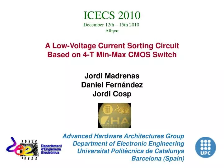
ICECS 2010 December 12th – 15th 2010 Αθηνα A Low-Voltage Current Sorting Circuit Based on 4-T Min-Max CMOS Switch Jordi Madrenas Daniel Fernández Jordi Cosp Advanced Hardware Architectures Group Department of Electronic Engineering Universitat Politècnica de Catalunya Barcelona (Spain)
OUTLINE • Introduction. • Low-voltage-drop min-max switch. • Four-input current sorting circuit. • 4 Simulation results. • 5 Conclusion.
1INTRODUCTION • Analog / mixed-signal processing • Characteristics of mixed-signal processing • Reduced precision. • Sensitivity to mismatch, temperature, noise, ... • Compact. • High-speed. • Low-power consumption. • Well-adapted for sensor processing (analog form). • Current mode style: Low-voltage/low-power.
1INTRODUCTION • Analog / mixed-signal processing • Sorter application examples: • Pattern recognition. • Median filtering. • K-winner(loser)-take-all.
1INTRODUCTION I2 I1 Self-controlled 4-transistor current switch V2 V1 M2A M1B M2B M1A IMIN IMAX VREF VREF It consists of two cross-coupled current mirrors
1INTRODUCTION Self-controlled 4-transistor current switch Cross-point transient measurement DC characteristic simulation
1INTRODUCTION Sorting with the 4-transistor current switch • Interesting properties • Input currents are not mirrored. • Very compact and low power. • Main limitations for multi-input (multi-stage) sorting • VTH voltage drop. • VREF needs to be kept equal for both outputs.
2Low-voltage-drop min-max switch I1 I2 V1 V2 Sample/Hold min-max switch SAMPLE SAMPLE • SAMPLE: min-max calculation. M2A M1A M1B M2B C2 C1 IMIN IMAX VREF VREF VDD • HOLD: Minimizes voltage drop after sampling. • BYPASS: Minimizes voltage drop before sampling. C1 HOLD BYPASS C2
2Low-voltage-drop min-max switch CVSL latch VDD VDD BYPASS BYPASS C2 C1 VDD VDD HOLD HOLD VDD C1 HOLD C2 C1 HOLD BYPASS C2 HOLD
2Low-voltage-drop min-max switch Sorting basic block I2 I1 HOLD HOLD1 Latch Switch SAMPLE SAMPLE1 BYPASS BYPASS1 Imin Imax
3Four-input current sorting circuit 4 3 2 1 3 4 1 2 IMIN IMIN IMAX IMAX 3 1 4 2 1 3 2 4 IMIN 1 2 3 4 IMAX
4Simulation results BYPASS2 BYPASS3 BYPASS3 SAMPLE2 SAMPLE3 Control signals SAMPLE1 HOLD1 HOLD1 HOLD2 H.1 H. 2 H. 3 time (µs)
4Simulation results Input currents time (µs)
4Simulation results Output currents time (µs)
5 CONCLUSION • Compact, low-voltage current-mode sorting circuit. • No need to replicate input currents. • Output currents exactly follow input currents (except leakage). • Ranking digital value is obtained by backtracing the CVSL latches. • Voltage drop of each stage ~ tens of millivolts. • Sequence of digital signals. • Generated using a simple Finite State Machine (FSM). • Alternatively self-timed logic can be used. • Correct simulation behavior for a 4-input sorter • 0.35 μm CMOS • VDD = 1.2 V • Sorts in 1 μs • Future implementation in 150 nm CMOS process.