Download
1 / 78
830 likes | 1.07k Views
Chapter 28 Formal Methods. Software Engineering: A Practitioner’s Approach, 6th edition by Roger S. Pressman. Problems with Conventional Specification. contradictions ambiguities vagueness incompleteness mixed levels of abstraction. Formal Specification.

E N D
Chapter 28Formal Methods Software Engineering: A Practitioner’s Approach, 6th edition by Roger S. Pressman
Problems with Conventional Specification • contradictions • ambiguities • vagueness • incompleteness • mixed levels of abstraction
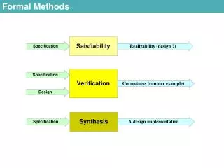
Formal Specification • Desired properties—consistency, completeness, and lack of ambiguity—are the objectives of all specification methods • The formal syntax of a specification language (Section 28.4) enables requirements or design to be interpreted in only one way, eliminating ambiguity that often occurs when a natural language (e.g., English) or a graphical notation must be interpreted • The descriptive facilities of set theory and logic notation (Section 28.2) enable clear statement of facts (requirements). • Consistency is ensured by mathematically proving that initial facts can be formally mapped (using inference rules) into later statements within the specification.
Formal Methods Concepts • data invariant—a condition that is true throughout the execution of the system that contains a collection of data • state • Many formal languages, such as OCL (Section 28.5) , use the notion of states as they were discussed in Chapters 7 and 8, that is, a system can be in one of several states, each representing an externally observable mode of behavior. • The Z language (Section 28.6)defines a state as the stored data which a system accesses and alters • operation—an action that takes place in a system and reads or writes data to a state • precondition defines the circumstances in which a particular operation is valid • postcondition defines what happens when an operation has completed its action
States and Data Invariant The state of the spooler is represented by the four components Queues, OutputDevices, Limits, and Sizes. The data invariant has five components: • Each output device is associated with an upper limit of print lines • Each output device is associated with a possibly nonempty queue of files awaiting printing • Each file is associated with a size • Each queue associated with an output device contains files that have a size less than the upper limit of the output device • There will be no more than MaxDevs output devices administered by the spooler
Operations • An operation which adds a new output device to the spooler together with its associated print limit • An operation which removes a file from the queue associated with a particular output device • An operation which adds a file to the queue associated with a particular output device • An operation which alters the upper limit of print lines for a particular output device • An operation which moves a file from a queue associated with an output device to another queue associated with a second output device
Pre- & Postconditions For the first operation (adds a new output device to the spooler together with its associated print limit): Precondition: the output device name does not already exist and that there are currently less than MaxDevs output devices known to the spooler Postcondition: the name of the new device is added to the collection of existing device names, a new entry is formed for the device with no files being associated with its queue, and the device is associated with its print limit.
Mathematical Concepts • sets and constructive set specification • set operators • logic operators • e.g., i, j: • i > j i2 => j2 • which states that, for every pair of values in the set of natural numbers, if i is greater than j, then i2 is greater than j2. • sequences
Sets and Constructive Specification • A set is a collection of objects or elements and is used as a cornerstone of formal methods. • Enumeration • {C++, Pascal, Ada, COBOL, Java} • #{C++, Pascal, Ada, COBOL, Java} implies cardinality = 5 • Constructive set specification is preferable to enumeration because it enables a succinct definition of large sets. • {x, y : N | x + y = 10 (x, y2)}
Set Operators • A specialized set of symbology is used to represent set and logic operations. • Examples • The P operator is used to indicate membership of a set. For example, the expression • x P X • The operators , , and # take sets as their operands. The predicate • A , B • has the value true if the members of the set A are contained in the set B and has the value false otherwise. • The union operator, <, takes two sets and forms a set that contains all the elements in the set with duplicates eliminated. • {File1, File2, Tax, Compiler} < {NewTax, D2, D3, File2} is the set • {Filel, File2, Tax, Compiler, NewTax, D2, D3}
Logic Operators • Another important component of a formal method is logic: the algebra of true and false expressions. • Examples: • V or • ¬ not • => implies • Universal quantification is a way of making a statement about the elements of a set that is true for every member of the set. Universal quantification uses the symbol, . An example of its use is • i, j : Ni > j => i2 > j2 • which states that for every pair of values in the set of natural numbers, if i is greater than j, then i2 is greater than j2.
Sequences • Sequences are designated using angle brackets. For example, the preceding sequence would normally be written as • k Jones, Wilson, Shapiro, Estavezl • Catenation, X, is a binary operator that forms a sequence constructed by adding its second operand to the end of its first operand. For example, • k 2, 3, 34, 1lXk12, 33, 34, 200 l = k 2, 3, 34, 1, 12, 33, 34, 200 l • Other operators that can be applied to sequences are head, tail, front, and last. • head k 2, 3, 34, 1, 99, 101 l = 2 • tail k 2, 3, 34, 1, 99, 101 l = 73, 34, 1,99, 1018 • lastk 2, 3, 34, 1, 99, 101 l = 101 • front k 2, 3, 34, 1, 99, 101 l = 72, 3, 34, 1, 998
Formal Specification • The block handler • The block handler maintains a reservoir of unused blocks and will also keep track of blocks that are currently in use. When blocks are released from a deleted file they are normally added to a queue of blocks waiting to be added to the reservoir of unused blocks. • The state used, free: PBLOCKS BlockQueue: seqPBLOCKS • Data Invariant used>free = \ used<free = AllBlocks i: dom BlockQueueBlockQueuei#used i, j : dom BlockQueuei≠j => BlockQueue i>BlockQueue j = \ • Precondition #BlockQueue > 0 • Postcondition used' = used \ headBlockQueue free’ = free<head BlockQueue BlockQueue' = tail BlockQueue
Formal Specification Languages • A formal specification language is usually composed of three primary components: • a syntax that defines the specific notation with which the specification is represented • semantics to help define a "universe of objects" [WIN90] that will be used to describe the system • a set of relations that define the rules that indicate which objects properly satisfy the specification • The syntactic domain of a formal specification language is often based on a syntax that is derived from standard set theory notation and predicate calculus. • The semantic domain of a specification language indicates how the language represents system requirements.
Object Constraint Language (OCL) • a formal notation developed so that users of UML can add more precision to their specifications • All of the power of logic and discrete mathematics is available in the language • However the designers of OCL decided that only ASCII characters (rather than conventional mathematical notation) should be used in OCL statements.
OCL Overview • Like an object-oriented programming language, an OCL expression involves operators operating on objects. • However, the result of a complete expression must always be a Boolean, i.e. true or false. • The objects can be instances of the OCL Collection class, of which Set and Sequence are two subclasses. • See Table 28.1 for summary of OCL notation
BlockHandler in OCL • No block will be marked as both unused and used. • context BlockHandler inv: • (self.used->intersection(self.free)) ->isEmpty() • All the sets of blocks held in the queue will be subsets of the collection of currently used blocks. • context BlockHandler inv: • blockQueue->forAll(aBlockSet | used->includesAll(aBlockSet )) • No elements of the queue will contain the same block numbers. • context BlockHandler inv: • blockQueue->forAll(blockSet1, blockSet2 | • blockSet1 <> blockSet2 implies • blockSet1.elements.number->excludesAll(blockSet2.elements.number)) • The expression before implies is needed to ensure we ignore pairs where both elements are the same Block. • The collection of used blocks and blocks that are unused will be the total collection of blocks that make up files. • context BlockHandler inv: • allBlocks = used->union(free) • The collection of unused blocks will have no duplicate block numbers. • context BlockHandler inv: • free->isUnique(aBlock | aBlock.number) • The collection of used blocks will have no duplicate block numbers. • context BlockHandler inv: • used->isUnique(aBlock | aBlock.number)
The Z Language • organized into schemas • defines variables • establishes relationships between variables • the analog for a “module” in conventional languages • notation described in Table 28.2
BlockHandler in Z The following example of a schema describes the state of the block handler and the data invariant: ———BlockHandler—————————————— used, free : PBLOCKS BlockQueue : seq PBLOCKS ——————————————————————— used>free = \ used<free = AllBlocks i: dom BlockQueueBlockQueuei#used i, j : dom BlockQueuei≠j => BlockQueue i>BlockQueue j = \ ———————————————————————— See Section 28.6.2 for further expansion of the specification
Chapter 29Cleanroom Software Engineering Software Engineering: A Practitioner’s Approach, 6th edition by Roger S. Pressman
The Cleanroom Strategy-I Increment Planning—adopts the incremental strategy Requirements Gathering—defines a description of customer level requirements (for each increment) Box Structure Specification—describes the functional specification Formal Design—specifications (called “black boxes”) are iteratively refined (with an increment) to become analogous to architectural and procedural designs (called “state boxes” and “clear boxes,” respectively). Correctness Verification—verification begins with the highest level box structure (specification) and moves toward design detail and code using a set of “correctness questions.” If these do not demonstrate that the specification is correct, more formal (mathematical) methods for verification are used. Code Generation, Inspection and Verification—the box structure specifications, represented in a specialized language, are transmitted into the appropriate programming language.
The Cleanroom Strategy-II Statistical Test Planning—a suite of test cases that exercise of “probability distribution” of usage are planned and designed Statistical Usage Testing—execute a series of tests derived from a statistical sample (the probability distribution noted above) of all possible program executions by all users from a targeted population Certification—once verification, inspection and usage testing have been completed (and all errors are corrected) the increment is certified as ready for integration.
Box Structure Specification black box clear box state box
Box Structures black box state box clear box
Design Refinement & Verification If a function f is expanded into a sequence g and h, the correctness condition for all input to f is: • Does g followed by h do f? When a function f is refined into a conditional (if-then-else), the correctness condition for all input to f is: • Whenever condition <c> is true does g do f and whenever <c> is false, does h do f? When function f is refined as a loop, the correctness conditions for all input to f is: • Is termination guaranteed? • Whenever <c> is true does g followed by f do f, and whenever <c> is false, does skipping the loop still do f?
Advantages of Design Verification • It reduces verification to a finite process. • It lets cleanroom teams verify every line of design and code. • It results in a near zero defect level. • It scales up. • It produces better code than unit testing.
Cleanroom Testing • statistical use testing • tests the actual usage of the program • determine a “usage probability distribution” • analyze the specification to identify a set of stimuli • stimuli cause software to change behavior • create usage scenarios • assign probability of use to each stimuli • test cases are generated for each stimuli according to the usage probability distribution
Certification 1. Usage scenarios must be created. 2. A usage profile is specified. 3. Test cases are generated from the profile. 4. Tests are executed and failure data are recorded and analyzed. 5. Reliability is computed and certified.
Certification Models Sampling model. Software testing executes m random test cases and is certified if no failures or a specified numbers of failures occur. The value of m is derived mathematically to ensure that required reliability is achieved. Component model. A system composed of n components is to be certified. The component model enables the analyst to determine the probability that component i will fail prior to completion. Certification model. The overall reliability of the system is projected and certified.
Chapter 30Component-BasedSoftware Engineering Software Engineering: A Practitioner’s Approach, 6th edition by Roger S. Pressman
The Key Questions • When faced with the possibility of reuse, the software team asks: • Are commercial off-the-shelf (COTS) components available to implement the requirement? • Are internally-developed reusable components available to implement the requirement? • Are the interfaces for available components compatible within the architecture of the system to be built? • At the same time, they are faced with the following impediments to reuse ...
Impediments to Reuse • Few companies and organizations have anything that even slightly resembles a comprehensive software reusability plan. • Although an increasing number of software vendors currently sell tools or components that provide direct assistance for software reuse, the majority of software developers do not use them. • Relatively little training is available to help software engineers and managers understand and apply reuse. • Many software practitioners continue to believe that reuse is “more trouble than it’s worth.” • Many companies continue to encourage of software development methodologies which do not facilitate reuse • Few companies provide an incentives to produce reusable program components.
Domain Engineering 1. Define the domain to be investigated. 2. Categorize the items extracted from the domain. 3. Collect a representative sample of applications in the domain. 4. Analyze each application in the sample. 5. Develop an analysis model for the objects.
Identifying Reusable Components • Is component functionality required on future implementations? • How common is the component's function within the domain? • Is there duplication of the component's function within the domain? • Is the component hardware-dependent? • Does the hardware remain unchanged between implementations? • Can the hardware specifics be removed to another component? • Is the design optimized enough for the next implementation? • Can we parameterize a non-reusable component so that it becomes reusable? • Is the component reusable in many implementations with only minor changes? • Is reuse through modification feasible? • Can a non-reusable component be decomposed to yield reusable components? • How valid is component decomposition for reuse?
Structural Modeling • every application has structural patterns that have the potential for reuse • a “structure point” is a construct with the structure • A structure point is an abstraction that should have a limited number of instances. Restating this in object-oriented jargon , the size of the class hierarchy should be small. • The rules that govern the use of the structure point should be easily understood. In addition, the interface to the structure point should be relatively simple. • The structure point should implement information hiding by hiding all complexity contained within the structure point itself. This reduces the perceived complexity of the overall system.
Structural Patterns • An interface that enables the user to interact with the system. • A bounds-setting mechanism that allows the user to establish bounds on the parameters to be measured. • A sensor management mechanism that communicates with all monitoring sensors. • A response mechanism that reacts to the input provided by the sensor management system. • A control mechanism that enables the user to control the manner in which monitoring is carried out.
Component-Based Development • a library of components must be available • components should have a consistent structure • a standard should exist, e.g., • OMG/CORBA • Microsoft COM • Sun JavaBeans
CBSE Activities • Component qualification • Component adaptation • Component composition • Component update
Qualification Before a component can be used, you must consider: • application programming interface (API) • development and integration tools required by the component • run-time requirements including resource usage (e.g., memory or storage), timing or speed, and network protocol • service requirements including operating system interfaces and support from other components • security features including access controls and authentication protocol • embedded design assumptions including the use of specific numerical or non-numerical algorithms • exception handling
Adaptation The implication of “easy integration” is: (1) that consistent methods of resource management have been implemented for all components in the library; (2) that common activities such as data management exist for all components, and (3) that interfaces within the architecture and with the external environment have been implemented in a consistent manner.
Composition • An infrastructure must be established to bind components together • Architectural ingredients for composition include: • Data exchange model • Automation • Structured storage • Underlying object model
OMG/ CORBA • The Object Management Group has published a common object request broker architecture (OMG/CORBA). • An object request broker (ORB) provides services that enable reusable components (objects) to communicate with other components, regardless of their location within a system. • Integration of CORBA components (without modification) within a system is assured if an interface definition language (IDL) interface is created for every component. • Objects within the client application request one or more services from the ORB server. Requests are made via an IDL or dynamically at run time. • An interface repository contains all necessary information about the service’s request and response formats.
Microsoft COM • The component object model (COM) provides a specification for using components produced by various vendors within a single application running under the Windows operating system. • COM encompasses two elements: • COM interfaces (implemented as COM objects) • a set of mechanisms for registering and passing messages between COM interfaces.
Sun JavaBeans • The JavaBeans component system is a portable, platform independent CBSE infrastructure developed using the Java programming language. • The JavaBeans component system encompasses a set of tools, called the Bean Development Kit (BDK), that allows developers to • analyze how existing Beans (components) work • customize their behavior and appearance • establish mechanisms for coordination and communication • develop custom Beans for use in a specific application • test and evaluate Bean behavior.
Classification • Enumerated classification—components are described by defining a hierarchical structure in which classes and varying levels of subclasses of software components are defined • Faceted classification—a domain area is analyzed and a set of basic descriptive features are identified • Attribute-value classification—a set of attributes are defined for all components in a domain area