Download
1 / 14
140 likes | 202 Views
Mu2e Magnet Design Changes. Contributors to the Mu2e Solenoid Design:

E N D
Mu2e Magnet Design Changes Contributors to the Mu2e Solenoid Design: N. Andreev, G. Ambrosio, R. Bossert, J. Brandt, M. Buehler, R. Coleman, D. Evbota, W. Jaskierny, V.V. Kashikhin, M. Lopes, J. Miller, T. Nicol, D. Orris, R. Ostojic, T. Page, T. Peterson, J. Popp, V, Pronskikh, Z. Tang, M. Tartaglia, Z. Tang, M. Wake, R. Wands and R. Yamada Michael Lamm for the Mu2e Collaboration and TD/Magnet Systems Dept. All Experimenters Meeting
Measure the Rare Process: m- + N e- + N Mu2e experiment consists of 3 solenoid systems: Production Solenoid Transport Solenoid Detector Solenoid 1.0T protons e- m-, p- 2.5T 4.6T Production Target Stopping Target 2.0T Tracker Calorimeter Collimators Muon timing is important. Negative axial field gradients prevent unwanted trapped particles from entering “Search Window”
Reason for Design Changes • Recommendations from May 2011 Independent Design Review • More operating margin for PS • Simplify DS • Better mechanical support for PS coils • Value Management exercise in Fall 2011 • Reduce cost of Solenoid project by ~$20M • Change in requirements • Field requirements have become less stringent with detailed beam studies Simplify magnet designs All Experimenters Meeting
L2 Solenoid Changes Since May 2011 IDR 4.6 T peak field Less layers for PS • Production Solenoid (PS) • Transport Solenoid (TS) • Detector Solenoid (DS) • Cryogenic Distribution PS IRON Single Layer-shorter Spectrometer DS IRON • Power Supply/Quench Protection • Cryoplant • Field Mapping • Ancillary Equipment • Insulating vacuum • Installation and commissioning DOWN SCALED DOWN SCALED OFF PROJECT
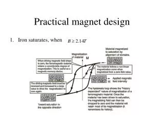
PS Baseline Design Changes Gradient made by 3 axial coils same turn density but change # of layers Wound on individual bobbins • Peak field 5T- I operation ~10kA • NbTi Rutherford cable + Ni doped aluminum stabilizer (like ATLAS CS) • Indirect Cooling (Thermal Siphon) • Hadron absorber intercepts beam secondaries • ~20 Watts deposited in coils • Nominal peak field 4.6T • 5T still possible with reduced margin • Reduce number of layers • Thinner conductor (lower current) • Remove iron yoke All Experimenters Meeting
PS Field vs. Tolerance Bands Meets 5% field uniformity spec All Experimenters Meeting
Collaboration with Japan Fabrication of practice PS coil at Toshiba (4 Layer/8 Turns) Uses aluminum stabilized NbTi conductor from Hitachi Cable Coil will be later tested at Fermilab All Experimenters Meeting
New baseline Transport Solenoid • TS1,TS3,TS5: Straight sections with axial gradient • TS2/TS4: approximate toroidal field • Accomplished by many thin solenoid rings of different amp-turns TS2 TS1 • ThreeTwo cryostats: TSU, TSD Rotatable Collimator, P-bar window • TS3: TS3U, TS3D. Wider coils to compensate for gap TS4 • New coil fabrication proposed for better mechanical support. G. Ambrosio TS Leader TS5 All Experimenters Meeting
Coil Fabrication Al Outer Supports Conductor Bolted connections • Original plan: use SS inner bobbins mechanical support complications. • New plan: fabrication unit consists of two coils with outer support aluminum structure • Coils wound on collapsible mandrel-then fit into outer aluminum ring • Placement of coil in transport is determined by outer shell geometry All Experimenters Meeting
TS Field Requirements • All sections meet all requirements • Large margin wrt gradient requirement Axial field distribution in the center of TS3 (left), axial gradient along TS3 (right). All Experimenters Meeting
Simplify DS Baseline • OLD base line • Two coils: gradient + spectrometer bussed in series in a single cryostat • Two layer spectrometer, single mandrel field uniformity • Two layer gradient on single mandrel with aluminum spacers • Iron return yoke (not shown) Gradient Section Spectrometer Section All Experimenters Meeting
Simplify DS Baseline • New base line driven by relaxed field requirements • Modular coil design reduced cost/coil • Spectrometer: 3 Single Layer Coils shorter coils, greatly reduced conductor volume, reduced field uniformity OK • Original conductor cost estimate based on expensive PS conductor, smaller field DS requires smaller cross section, no need for special reinforced aluminum • Relaxed calorimeter field requirements shorten spectrometer Gradient Section Spectrometer Section All Experimenters Meeting
DS Field vs. Tolerance Bands Gradient Section Spectrometer Section All Experimenters Meeting
Conclusion • Significant amount of work done prior to CD1 • Conceptual design of solenoids • Technology development with Japan • Near term schedule • CD1 directors review April 3-5, Lehman review in June • June 2012-2014 • Test Toshiba coil/built prototype TS module/prototype conductor • CD2 sometime in 2014 • Order conductor/ Contract final design with industry • Begin fabrication in 2016 All Experimenters Meeting