Download

1 / 19
200 likes | 475 Views
Lecture 32 DC Motors Part II. Learning Objectives. Analyze the circuit equivalent of a permanent magnetic DC motor that accounts for armature resistance, induced electromotive force (back EMF), developed electromagnetic torque, and applied (input) voltage.

E N D
Learning Objectives • Analyze the circuit equivalent of a permanent magnetic DC motor that accounts for armature resistance, induced electromotive force (back EMF), developed electromagnetic torque, and applied (input) voltage. • Define the power output of a permanent magnetic DC motor in terms of developed electromagnetic torque and angular velocity. Relate power output in terms of horse power. • Determine the efficiency of a permanent magnetic DC motor using the given or calculated power in and power out.
Parts of a DC Motor SOURCE: Gears Educational Systems.
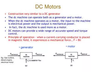
Rotary DC Motor • Torque developed Td=Kv Ia • Power DevelopedPd = Td ω = Kv Ia ω • Back EMF Ea = Kv ω • Angular velocity ω = 2 (RPM/60)
DC motor power flow Pelec loss Pmech loss Pout Pin Pdev = Pout + Pmechloss
Electrical Power losses Electrical loss occurs due to the armature resistance and is expressed as Pelec loss = Ia2 Ra. Pelec loss
Torque losses (Tloss) Pmech loss represents losses due to the friction of mechanical parts, magnetic inefficiencies of the material, and losses coupling brushes and commutator and is expressed as Pmech loss = Tlosswm Pmech loss
Pd represents the powerdeveloped by the motor which includes power out and mechanical losses (Ploss). It is expressed Pd = Pmech loss + Pout = Tdevw = Kv IAwm Power out is the power that ultimately gets to the load and is expressed Pout = TLOADwm Output Power Pout Pd = Pout + Pmech loss
Power Conversion Diagram Electrical Mechanical
Motor Efficiency • Developed power is: • If we Ignore rotational losses, Pd=Pout, and machine efficiency can be calculated as:
Instead of permanent magnet, we could raise the field strength B with an electromagnet. The wires wrapped around a ferromagnetic core are known as field windings. The field windings are stationary and are part of the stator. Magnetic field
Magnetic field 2 poles
Increasing the number of poles will increase and smooth the output torque. four-pole dc machine Magnetic poles eight-pole dc machine
Example Problem 1 A 24 V DC motor is rated for 15 A. RA = 0.20 Ω Assumed no rotational losses. Determine: • The input power • The power loss due to the resistance of the armature • The power developed • The back EMF (EA) • The efficiency assuming no mechanical power loss • Draw a power conversion diagram and fill-in the values for power in, electrical power loss, power developed, mechanical power loss and power out.
Example Problem 2 A permanent magnet DC motor is rated for 120V, 17A and 1200 rpm. The machine is 90% efficient at rated conditions Tloss = 0.0334 N·m Find Raand Kv and torque developed by the motor .
Example Problem 3 We wish to design a 1/4 hp, 28 V DC motor with an efficiency of 96%. What current can we expect to draw? If the machine constant is Kv= 0.2139 ν·s, determine Tout if we ignore mechanical losses. Calculate rated speed in rpm.
FIELD ARMATURE Why is there so much field wiring on the Practical Exercise?
PE 20 Diagram FIELD ARMATURE