Download

1 / 60
660 likes | 845 Views
Heating systems. Source of heat. 99.9% of the cars on the road today use waste heat from the engine cooling system to provide cabin heat. This heat energy would normally be lost to the radiator.

E N D
Source of heat • 99.9% of the cars on the road today use waste heat from the engine cooling system to provide cabin heat. • This heat energy would normally be lost to the radiator. • Electric heating grids are used on electric vehicles [Nissan Leaf] and plug in electric vehicles [Chevy Volt and Prius Plug-in]. • Electric cabin heat uses energy from the battery, reducing the range the vehicle can travel in electric mode. • Exhaust heat was used for vehicles with air cooled engines [older Porsche 911 and VW Beetle]
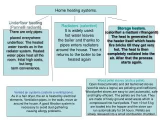
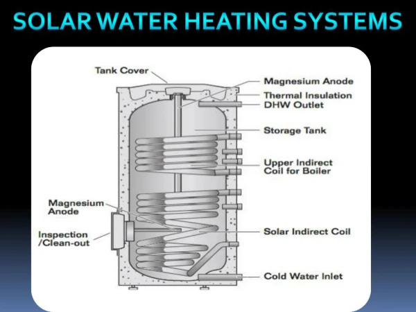
Cooling system • The cabin air is heated by the air passing through the heater core. • The heater core uses hot coolant that would otherwise flow through the radiator. Hot coolant from cylinder head Radiator Heater core Coolant return to water pump
Heater core • The heater core is a heat exchanger. • Heat from the coolant is transferred to the air passing through the fins. • The heater core shown here has an aluminum core and plastic side tanks.
Heater core • The heater core is essentially a mini radiator. • Hot coolant passes through thin flat tubes. • Fins attached to the tubes provide additional surface area for heat to be transferred to the air passing between the tubes. Coolant tubes Coolant flow Fins Air flow
Brass heater core • Brass heater cores are normally found on older vehicles. • Solder is used to join the components of the brass heater core. • Unlike aluminum, brass heater cores can be repaired. Foam rubber prevents air bypassing the heater core
Heater core – side tanks Side tank • Inlet and outlet tubes are located on the heater core’s side tanks. • If both inlet and outlet tubes are on the same side of the core there must be a baffle in the tank to separate the inlet and outlet sections. Inlet Side tank Outlet Baffle
Heater hoses • The heater core is normally located inside a heater box on the cabin side of the firewall. • The inlet and outlet tubes extend through a hole in the firewall where the heater hoses can be attached. • The extra connections shown on this van are for a rear heater core. Heater core tubes Rear heater coolant lines
Heater hoses • Heater hoses are reinforced flexible rubber hoses used to connect the engine to the heater core. • The engine rotates slightly on the engine mounts as torque is applied to the wheels. • The heater hoses must flex to accommodate the rotation of the engine. • Metal pipes are used to conduct coolant in places where there will be no movement – such as lines to rear cabin heater cores.
Molded heater hose vs. replacement hose • OEM [Original Equipment Manufacturer] hoses a molded to custom fit the application. • Generic heater hose can be purchased in various inner diameters by the foot from a part store. • Generic heater hose cannot be bent through sharp angles – it will kink – restricting the flow of coolant if bent through too small a radius. • Wire wound generic heater hose will not kink. • OEM heater hoses purchased through a dealer is the best method of repair.
Heater shutoff valve • The heater shutoff valve blocks the flow of coolant through the heater core when the A/C system is set to A/C max or the temperature control is set to it’s coldest position. • The shutoff valve can be mounted on the heater core or under the hood
Heater shutoff valve • The shutoff valve must have a shaft seal to prevent coolant loss at the point where the shaft enters the valve housing. • The shutoff valve is operated by a cable or vacuum diaphragm.
Vacuum operated heat cutoff valve Heater hose • When vacuum is applied to the valve shown here the flow of coolant through the heater core is shut off. • This valve is open whenever there is no vacuum applied [fail safe position] Vacuum chamber Vacuum Line Blower motor resistor
Heater fan • Air is circulated through the heater core by an electrically driven ‘squirrel cage’ fan. • Air enters the center of the fan. • The rotation of the squirrel cage pushes the air outward by centrifugal force. • The housing catches the air and sends it on to the heater box assembly. Centrifugal force pushes the air outward Air enters through the center of the squirrel cage
Fan motor speed control Medium speed • A series of wire resistors is used to control the speed of the electric motor. • Some electronic climate control systems will use a fan control transistor to regulate fan speed. Base speed Low speed Diode
Resistor block • The blower motor resistors get very hot when the electric motor is running. • To keep the resistors cool the resistor block assembly is located in the heater box[heater case] directly downstream from the blower fan. • The resistor assembly is normally retained by two screws and is usually easy to service. • Removing the resistor assembly can sometimes allow the technician to get a peak at the evaporator without having to remove the entire heater box assembly.
Blower motor speed control • The electric motor that drives the heater fan is called the blower motor. • The ‘fan motor’ is the electric motor that drives the radiator fan. • Since 1977 all cars run the blower motor at very low speed whenever the ignition key is on. • This is intended to prevent injury from carbon monoxide poisoning when the vehicle is not moving but the engine is running to provide heat.
Blower motor • The blower motor is typically attached to the heater box by 4 screws and can be easily replaced. • You can easily test the operation of the motor using jumper wires. • Most blower motors draw between 10 and 30 amps.
Blower motor circuit Resistor block The blower motor circuit is made up of: • Fan switch • Ignition switch • Blower motor Fan switch Ignition switch 15 amp fuse Blower motor 30 amp fuse High speed relay • Resistor block • High speed relay • 2 fuses
Ignition on – fan switch off • When the ignition switch is turned on power flows through R1 to the motor. • If R1 is a 10 ohm resistor the motor will receive 1.2 amps of current [about 5% of the motors capacity]. Fan switch Ignition switch 15 amp fuse
Ignition on – fan switch on ‘Low’ • When the fan switch is turned to low power flows through R2 and R3 then on to the blower motor. • If R2 is a 2 ohm resistor and R3 is a 1 ohm resistor the motor will receive 4 amps of electric current. [20%] Fan switch Ignition switch 15 amp fuse
Ignition on – fan switch on ‘Med’ • When the fan switch is turned to medium power flows through R3 then on to the blower motor. • If R3 is a 1 ohm resistor the motor will receive 6 amps of electric current. [33%] Fan switch Ignition switch 15 amp fuse
Ignition on – fan switch on ‘High’ • When the fan switch is turned to high, the fan switch energizes the electromagnet in the high speed relay. • The high speed relay allows full power to go to the blower motor. • Blower motors typically draw 20 to 30 amps of current. Fan switch Ignition switch 15 amp fuse 30 amp fuse Note: both fuses are needed for high speed operation 1/4 amp trigger current High speed relay 20 amp current flow
Electronic blower motor speed control HVAC control head • The blower motor speed is electronically controlled by the BCM [Body Control Module] on most late model cars. BCM Fuse box CAN network Cabin air temperature sensor Blower motor module [driver] Blower motor
Blower motor module • The blower motor module is a high speed electronic switch that turns the power to the electric motor on and off hundreds of times each second. • This type of electrical control is called a pulse width modulated duty cycle. 10 mS On 50% duty cycle Off 10 mS 1 mS =1/1000 second
Blower motor module • If the motor is turned on half the time and turned off half the time the motor runs at 50% of it potential speed. • If we send power to the motor for 1 millisecond and then turn the power off for 19 milliseconds the motor will run at 5 percent of its potential speed. 1 mS On 5% duty cycle Off 1 mS =1/1000 second 19 mS
Blower motor module • If we send power to the motor for 19 milliseconds and then turn the power off for 1 millisecond the motor now runs at 95 percent of its potential speed. 19 mS On 95% duty cycle Off 1 mS 1 mS =1/1000 second
Blower motor control module BCM to module communications • Some of the terminals on the blower motor module send cabin air temperature data back to the BCM 12 Volt + power feed 12 Volt + power feed
BCM and HVAC control head HVAC control head • When the driver presses the buttons on the HVAC control head a digital signal is sent to the BCM through the vehicle’s CAN network. • The BCM processes the request and sends the appropriate signals to the heating system actuators. BCM CAN network Network Interface chip Cabin air temperature sensor
Electronic blower motor control • On initial startup in cold weather the fan is usually turned off so that cold air is not blown onto the passengers. • If the cabin is cold and defrost mode is selected the fan will normally be commanded to high speed by the BCM. Electronic blower motor controller • The BCM may run the fan for a few minutes after engine shutdown to dry off the A/C evaporator. This helps prevent the formation of mold on the evaporator core.
Temperature control • There are two ways to manually control cabin temperature: • Heater valves regulate the flow of coolant through the heater core • Blend doors • Most cars use a blend door system that maintains a constant flow of hot coolant circulating through the heater core • Air temperature is controlled by a blend door that mixes heated and unheated air to achieve the desired cabin air temperature
Heater valve • Heater valves are normally located on the engine compartment side of the firewall where the heater hose meets the heater core inlet. • The heater valve is normally cable controlled. • Some times an electronically controlled stepper motor is used
Heater valves • The heater valve requires a seal where the valve shaft passes through the valve housing. • This seal is a potential source of coolant leakage • When the heater valve is located under the hood the cable is subject to corrosion which will cause binding and eventual cable failure.
Heater box Defrost outlet • The heater box is a plastic enclosure that contains the heater core, blower motor and mode doors. • The heater box is normally located on the cabin side of the firewall. • Fresh air from the cowl area enters the heater box through a large hole in the firewall. Fresh air inlet Heater core Face level outlet Blower motor Foot well outlet
Blend door – cold position Defrost outlet Blend door • The blend door controls the temperature of the air coming out of the air vents at the footwell, face level and defrost vents. • In the position shown here the air passage to the heater core is totally blocked by the blend door. • This forces all of the air to bypass the heater core. Heater core Face level outlet Blower motor Footwell outlet
Blend door – Hot position Defrost outlet • In the position shown here the bypass passage is blocked by the blend door. • This forces all of the air to pass through the heater core. Heater core Face level outlet Blower motor Blend door Footwell outlet
Blend door – mixed position Defrost outlet • In the position shown here the blend door is in-between the heater core and bypass passage . • Some of the air goes through the heater core – some bypasses it. Heater core Face level outlet Blower motor Footwell outlet
Mode doors – Footwell Defrost outlet • The footwell mode door diverts air to the defrost/face level duct or foot level outlet. • Most vehicles have a middle position allowing half of the air to be directed to the face level and haft to go to the footwell vents. Heater core Face level outlet Blower motor Footwell mode door Footwell outlet
Mode doors – Defrost Defrost outlet • When the footwell mode door is closed air is diverted into the defroster/face level duct. • A second mode door diverts air to either the defrost or face level vents. Heater core Face level outlet Defrost/face level mode door Blower motor Footwell mode door Footwell outlet
Mode doors – Face level Defrost outlet • The defrost / face level vents diverts air into the face level vents. • Most cars have individual valves and louvers on the face level vents so that air can be directed differently between the driver and passenger side. Heater core Face level outlet Defrost/face level mode door Blower motor Footwell mode door Footwell outlet
Heater box • To gain access to the heater core and mode doors the entire heater box may need to be removed from the vehicle. Studs attach the heater box to the fire wall Heater core
Recirculating mode • Recirculating mode doors are generally not found on vehicles that are not equipped with Air conditioning. • In recirculating mode the air entering the fan is taken from inside the cabin. Recirculation mode door in fresh air position
Recirculating mode • When the outside air temperature is high the air inside the cabin is cooler after the A/C has been running for a few minutes. • This reduces the amount of work the A/C compressor must do, which helps improve fuel economy while keeping the occupants comfortable. Recirculation mode door in ‘Recirc’ position
Blend and mode door actuators • There are 3 different methods of operating the blend and mod doors. • Cable • Vacuum diaphragm • Electric motor • Electric motors have become the dominant type of control in the past few years because they allow the vehicle electronic systems a greater degree of control of the HVAC system.
Cable actuators Mode door • Cable actuators work the same as the brake cables on a bicycle. Outer conduit Inner cable Clamp HVAC control head Clamp Operating lever
Cable actuators • One disadvantage of a cable is that it’s good at pulling but not so good at pushing. • If the blend door or mode door is binding the cable may be bent if the operator tries to force it. • Another disadvantage of cables is that they cannot operate through a sharp angle. • Cable systems are normally operated by horizontal levers in the control head.
Vacuum actuators Rubber diaphragm Vacuum chamber Vacuum hose • Vacuum actuators – sometimes called vacuum motors were very common in the 1970s and 1980s. • When no vacuum is applied spring tension pushes the actuating rod outward. Actuating rod Spring
Vacuum actuators 5 psi intake manifold pressure • When vacuum is applied to the actuator there is a 10 psi pressure difference operating on the diaphragm. • If the diaphragm has a surface area of 2 square inches 20 pounds of pulling force will be applied to the actuating rod. 15 psi atmospheric pressure Vacuum applied
Dual chamber vacuum actuators • Conventional vacuum actuators are generally either open or closed. • 3 position vacuum actuators are often used for mode control. • This allows for an open, ½ open and a closed position. Seal
Vacuum control To intake manifold • The vacuum actuators are controlled by a rotary valve in the HVAC control head. Check valve • A reserve of vacuum is needed for conditions when there is little or no manifold vacuum [hard acceleration, climbing hills etc]. • A check valve in the vacuum reservoir prevents air from entering the reservoir when vacuum is low Grommet Vacuum ball [reservoir] Rotary valve • Several rotary valves are combined into one assembly to control all the mode door actuators. HVAC control head