Download
1 / 10
110 likes | 286 Views
Fundamental Power Couplers for Crab Cavities. Possible designs. 4 rods. Outer line = 62 mm Inner Line = 27 mm End shape of the antenna : R 13.5 mm or shape to be provided Penetration length from cavity flange : P mm to be given Cavity port : Stainless Steel 316 LN flange

E N D
Fundamental Power Couplers for Crab Cavities Possible designs
4 rods • Outer line = 62 mm • Inner Line = 27 mm • End shape of the antenna : • R 13.5 mm or shape to be provided • Penetration length from cavity flange : • P mm to be given • Cavity port : • Stainless Steel 316 LN flange • Perpendicular to beam tube • Preferably on top of cavity 62 27 R13.5 P mm Crab Cavities Power Couplers 17 January 2013
Double Ridge • Outer line = 62 mm • Inner Line = 27 mm • End shape of the antenna : • R 13.5 mm or shape to be provided • Penetration length from cavity flange : • P mm to be given • Cavity port : • Stainless Steel 316 LN flange • Perpendicular to beam tube • Preferably on top of cavity 62 P mm 27 Crab Cavities Power Couplers 17 January 2013
Quarter Wave • Outer line = 62 mm • Inner Line = 27 mm • End shape of the antenna : • Special hook with no outer contact, shape to be given • Penetration length from cavity flange : • P mm to be given • Cavity port : • Stainless Steel 316 LN flange • Perpendicular to beam tube • Preferably on top of cavity 62 27 P mm Crab Cavities Power Couplers 17 January 2013
Double walled Tube tbd • CERN will provide a common Outer line to connect coupler to cavity : • Cavity flange DN63 • Cryomodule flange to be defined • Length to be defined • Cavity flange DN63 : • Inner diameter = 62 mm • Outer Diameter = 114 mm • CERN will also provide specific copper gasket with RF & Vacuum function tbd 114 mm 62 mm Crab Cavities Power Couplers 17 January 2013
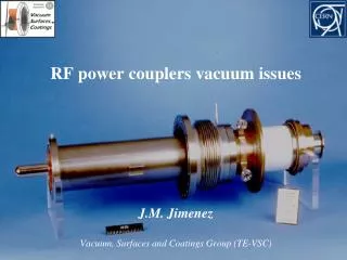
Windows • CERN will provide windows, bodies and Antennae • Length defined regarding cavity input port • These will be fully equipped with : • Vacuum gauge port • e- monitor • Glass window (arc detection) • Cooling of inner line with inner cane Crab Cavities Power Couplers 17 January 2013
Test Box • CERN will build 2 prototype windows per cavity design • CERN will also build : • 3 Test boxes (in order to keep all couplers clean after RF processing) • 6 Double walled Tubes Crab Cavities Power Couplers 17 January 2013
Cavity vacuum • As a first step, Windows + DT must be assembled in clean room to the cavity • This closes beam vacuum • It must be an ultra clean process Cavity and its helium vessel Crab Cavities Power Couplers 17 January 2013
Coupler to cavity • At a later stage, outside clean room, remaining items will be mounted • Cavity vessel will have to be robust enough to stand all these items : • Total Weight without air line : approximately 15 kg • Total Weight with air line (coaxial + WG) : approximately 35 kg Cryomodule Bellow between coupler and cryomudule Cavity and its helium vessel Crab Cavities Power Couplers 17 January 2013
Schedule • 3D drawings for approval : February 2013 • 2D drawings (EDMS): March 2013 • Prototypes ready for tests: March 2014 • Couplers ready for cavity assembly : December 2014 Crab Cavities Power Couplers 17 January 2013