Download
1 / 22
220 likes | 319 Views
Advanced Virgo – Nikhef tasks Jo van den Brand, Nikhef. June 16, 2009 - jo@nikhef.nl. Outline. Cryo links Sensing and control Longitudinal alignment Linear alignment Phase camera Suspension and bench systems Internal injection bench IMC end mirror Internal detection bench

E N D
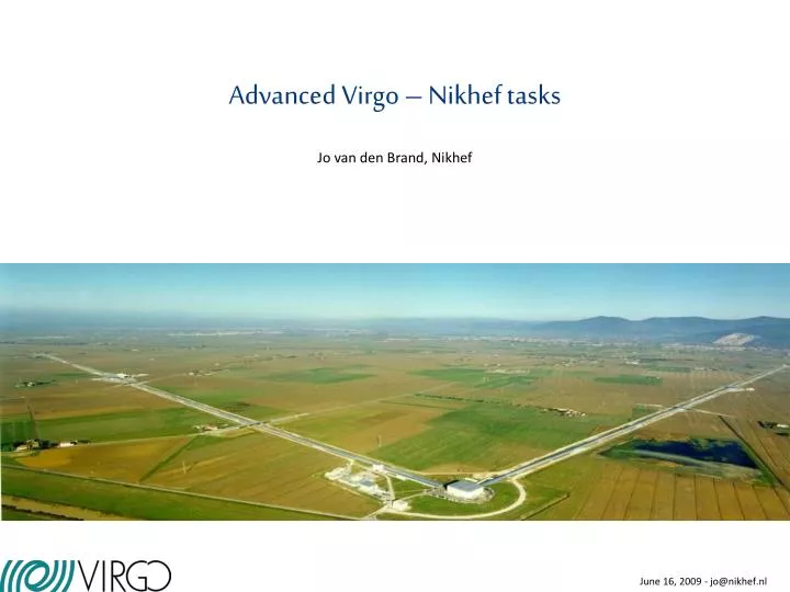
Advanced Virgo – Nikhef tasks Jo van den Brand, Nikhef June 16, 2009 - jo@nikhef.nl
Outline • Cryo links • Sensing and control • Longitudinal alignment • Linear alignment • Phase camera • Suspension and bench systems • Internal injection bench • IMC end mirror • Internal detection bench • External injection (laser bench) • External detection bench • External end benches • Einstein Telescope • Measurements • Homestake • Kamioka • Gran Sasso • FEA simulations GGN
Vacuum system • UHV (<10-9 mbar) • Two 3 km arms
West input Options: - small or large link - small link: small or large diameter Rotated DN1000 standard valve
West input Short cryo link
West input DN1000 standard valve DN630 standard valve (D = 650 mm) Ion pumps
West input Valve DN630 New valve position 700 for end stations Adapter
West / North end Mirror Cold surface: length: 2023 mm diameter: 1000 mm Baffles: diameter: 600 mm 3 needed to cover cold surface temperature influences mirror temperature material: stainless / glass?
Cryo link details LN2 vessel support superinsulation 3.2 mm/m Heat bridge/expansion bellows LN2 (200 l) Baffle D= 620 mm
Transfer line connections Rapid heatup 60 mm 34 mm LN2 inlet duct LN2 max level (control ± 10 mm) Bath width: 325 mm
Phase separator 2 m above cryo link
Performance • Expected water load: 10-4 mbar l/s • Q1 year = 3150 mbar l gas • 22,400 mbar l = 1 mol = 18 gram • Thus, expected load 0.14 mol or 2.5 gram water • Expected layer • Length 2.0 m, diameter 1 m, Area = pDL • Number of sites 1015 cm-2 • After 1 year expect 0.4 micron layer • Heat load and LN2 consumption • Depends on emissivity 0.1 – 0.2 • Heat load 200 – 300 W • LN2 consumption: 3.5 liter/hour • Expected gas load: 0.2 liter/s
Logistics • Quotations: total 789 kEuro (939 kEuro including VAT) • R&D phase 10 kEuro • Design & engineering 45 kEuro • Short link 125 kEuro x 4 • Standard phase separator • Simple LN2 extraction • Simplification of separation rings for LN2 circuit • Valve DN630 39.8 kEuro x 4 • ex VAT • ex 7.5% discount • Other items 75 kEuro • Valve DN100 • Turbo molecular pump station • Gauges, control, tubing, etc. • Manpower ~ 5 fte • Mechanical and control system design • Construction of (support) structures, etc • Testing • Installation M. Doets, E. Hennes, H. Boer Rookhuizen vdB
Cryo links – summary • Preliminary design for short cryo links • Length 2.0 m, diameter 1 m • Capacity > 1 year for 1 micron layer • Reduced heat load: 200 – 300 W • LN2 consumption: 3.5 liter/hour • Low gas load (0.2 liter/s), less bubbles, less noise • Thermal effect on mirrors acceptable • Reduced cost • Test set-up • Operations • External vs closed loop condensor • Consumption versus coverage (emissivity development) • Control issues (normal running, regeneration, …) • Bubble induced noise – perform tests
Sensing and control • Reference design: • Auxiliary laser to lock the high finesse cavities • Extended Variable Finesse technique for full lock • Requirements, a set of cavity lengths and mod. frequencies defined • Linear control scheme defined • The reference control strategy requires to move all the long towers in the central building
Noise in transimpedance amp • Simplified noise model • All noise source parallel except eN 100 mA and 1000 shot noise (100 mA) eN noise Dark current and Johnson noise
Improvements Amplifier (noise) 8.35 MHz (band filter) 9.4 MHz R&D 65.6 (quad diodes) Long. and linear alignment Demodulator boards Han Voet, VU Amsterdam
Measure wave fronts in cavity Phase camera H. Groenstege, H. Voet Ketel, vdB Phase camera- David Rabeling, H. Voet, etc. Han Voet, VU Amsterdam
Injection system • Input mode cleaner: 144 m suspended triangular cavity • Large Faraday isolator with thermal compensation (DKDP crystal) • Non degenerate PR cavity: the matching telescope is moved inside the cavity. The PRM and the folding mirror must be suspended on the injection bench
Suspension and bench systems • Mirrors and optical benches need to be suspended in vacuum • Injection bench: PRM1 • Detection bench: SRM3 • Input mode cleaner
Suspension and bench systems • External optical benches: >= 6 benches • External injection bench
Einstein Telescope: site selection and infrastructure • Newtonian noise • FEA crucial to determine • Depth • Cavity shape • Performance of ET • System design • Vacuum system • Hall, caverns, infrastructure • Cost estimates • Seismic data • Seismic measurements clay granite Eric Hennes ET will feature 100 – 200 m long cryogenic suspensions