Download
1 / 11
120 likes | 269 Views
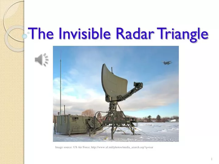
The Invisible Radar Triangle. Image source: US Air Force, http://www.af.mil/photos/media_search.asp?q=isar. What is radar imaging?. Radar imaging is used to detect objects that are far away.

E N D
The Invisible Radar Triangle Image source: US Air Force, http://www.af.mil/photos/media_search.asp?q=isar
What is radar imaging? • Radar imaging is used to detect objects that are far away. • Many different types of radar imaging have been created, but in this activity, we will look at inverse synthetic aperture radar (ISAR). • ISAR creates images of objects (targets) that are constantly moving (such as airplanes, cars, planets, etc.).
What about the triangle? • This drawing illustrates a radar imaging scenario. • The distance from the radar to the target is the slant range. • The horizontal distance from the radar to a point of reference on the ground under the target is the ground range. • The slant range, ground range and airplane’s altitude form an invisible right triangle. Do you see it?
Engineers use this invisible triangle and different equations to calculate the distance, direction and elevation angle of the target.
Why do we need radar imaging? • ISAR radar imaging is mainly used by government agencies for surveillance. • Engineers have designed many radar systems for many different uses. • For example, NASA uses different kinds of radars to study the Earth, other planets and space. • Radars are also used to monitor weather.
Radar imaging simulations • To continually improve existing radar imaging techniques, engineers have developed radar imaging simulators. • A radar imaging simulator uses a three-dimensional model of the target being studied to generate radar images and adjust parameters until the desired image quality is achieved. • Similarity and scaling are used to create three-dimensional scale models of targets. Image source: US Air Force, model of E-3, http://www.af.mil/photos/media_search.asp?q=radar imaging simulation&page=36
Imagine… Imagine you are an army soldier who monitors radar systems at a military base. You are asked to make a presentation to a group of people describing how radar imagining is done. Your audience is not familiar with radar imaging. You decide to use a model to help your audience better understand your presentation. Your model must be similar to the one shown in the presentation. Image source: US Air Force, http://www.af.mil/photos/media_search.asp?q=isar • How can a model help you present this concept?
You know the angle formed by the ground range and the airplane’s altitude is 90 degrees. You want to use an elevation angle of 37 degrees (formed by the ground range and slant range). • How can you determine the third angle in the triangle? • How can you make a realistic model of the scenario? • How can the concept of similar figures help you construct a proportional model to make it more realistic? 90° 37°
Let’s Plan • First, design your model on paper. • When you are done, show it to me.
Infrared range sensor • Radars send radio waves to a target, the waves reflect back and are stored and processed to produce an image. • Engineers use equations to calculate the distance between the radar and the airplane. • In our activity, we will use an infrared range sensor and a multimeterto calculate the distance between the radar and the airplane. • You will work in your groups to make and calibrate your sensors. Image source: 2012 RET-ENET Program, The University of Texas-Pan American
References • Wolff, Christian. “Synthetic Aperture Radar.” Accessed July 6, 2012. (inspiration for triangle diagram) http://www.radartutorial.eu/20.airborne/ab07.en.html#this • “Video Gallery.” NASA. Accessed July 6, 2012. http://www.nasa.gov/multimedia/videogallery/index.html