Download
1 / 101
1.02k likes | 1.16k Views
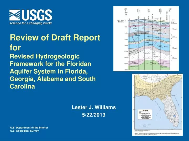
Review of Draft Report for Revised Hydrogeologic Framework for the Floridan Aquifer System in Florida, Georgia, Alabama and South Carolina. Lester J. Williams 5/22/2013. Meeting Objectives. Give you an overview of the draft hydrogeologic framework (45 min)

E N D
Review of Draft Report forRevised Hydrogeologic Framework for the Floridan Aquifer System in Florida, Georgia, Alabama and South Carolina Lester J. Williams 5/22/2013
Meeting Objectives • Give you an overview of the draft hydrogeologic framework (45 min) • Address selected comments and further explanation of issues that were brought up during the review (20 min) • Have an open discussion and question and answer session (1 hr) Study area showing cross section lines
USGS Regional Assessments • A key role of national and regional assessments is to provide consistent and integrated information across political boundaries that is useful to those who use and manage the resource. U.S. Geological Survey Circular 1323 (Published July 2008)
USGS Water Resource Program Goal: National Assessment of Groundwater Availability Floridan Aquifer System 30 principal aquifers account for 94% of total groundwater withdrawals
Project Background • One of several current ongoing studies being conducted by the USGS Groundwater Resource Program (GWRP) • Began in Fall of 2009 • Project Lead left in Fall of 2010 • Work continued on framework development in 2011-2012 • Funding lost in 2012 • Project restarted in 2013
Framework Revision RASA Framework • Focused on improving the physical geometry and understanding of the hydraulic properties of the system • Improve understanding of flow system needed to build numerical model • Active surficial • Salt-water encroachment 6 to 8 yrs Revised Framework 3.5 yrs (originally est. to be 2 yrs)
Framework Products • Geophysical Log Database • Framework Report • Digital Data (GIS) report • Saline Mapping Report
Floridan aquifer system: many ways to split the system into its permeable and less-permeable units SURFICIAL AQUIFER SYSTEM UPPER CONFINING UNIT (IAS/ICU) UPPER FLORIDAN AQUIFER MIDDLE CONFINING UNIT ? ? MIDDLE CONFINING UNIT LOWER FLORIDAN AQUIFER SALINE WATER
Hydraulic separation between UF and LF Small separation across the MCU (inches) Relatively larger separation (several feet) Richmond Hill, Bryan Co. Ga. ShellmanBluff, McIntosh Co. Ga. From Falls and others, 2005
Single to multi-aquifer problem • An aquifer is divided depending on: • Inherent complexity of the physical system • Amount of data available to describe the physical system
Lets say you have a new aquifer you are trying to define: Step 1 Initially not much may be known Well 1 TOP BOT
Lets say you have a new aquifer you are trying to define: Step 2 But… by the second or third well you may be able define units Well 2 Well 3 Well 1 TOP highly permeable zone less permeable, might be part of confining unit highly permeable zone confining highly permeable zone BOT
Lets say you have a new aquifer you are trying to define: Step 3 Finally we are starting to connect the dots and determine continuity and local variations Well 2 Well 4 Well 3 Well 1 TOP highly permeable zone less permeable, might be part of confining unit MCU highly permeable zone confining BOT highly permeable zone
Vertical vs. Horizontal Grouping? Cross Section View Map View Well 1 Well 2 MCU absent MCU Present UFA highly permeable zone 1-Layer UF Well 2 less permeable but not part of confining unit MCU Upper and Lower Floridan aquifers (two aquifer system) UFA Well 1 highly permeable zone 2-Layer UF/LF LFA less permeable highly permeable zone Well 3 Indicates similar hydraulic properties in adjacent wells for lower part of aquifer system In one well this sequence is part of the Lower Floridan (Well 2) and in the other case it is the lower part of the Upper Floridan
Increased use of zones to represent regional and local variations in permeability • Floridan Aquifer System • Upper and Lower Floridan aquifers • Middle confining unit • Zones divide aquifers into permeable and less permeable units
Zones • Located within an aquifer • Used to divide the aquifer into permeable and less-permeable units • Have stratigraphic context • There are no hard and fast rules to how thick or thin these can be but try to limit them vertically in the section
Mapping high and low-permeability zones • Usually have narrowly defined rock-stratigraphic position (formation or two adjacent formations) • Hydraulic testing used to define properties • Geophysical logs and markers used to map zones across subregional areas
If you only had flow logs which zone connects? Well 2 Well 1 flow increases flow increases
Mapping approach Waycross Ga. • First determine the presence or potential presence of zones of enhanced permeability supported by one or more flowmeter logs or other data • Plot these on working sections along with logs to evaluate position of flow zones with respect to stratigraphic units • Through iterative process determine the depth, stratigraphic position, and continuity of flow zones same approach is used for identifying low-permeability units!
Assumptions • Geophysical log patterns can be used to identify characteristic rock sequences whose physical properties control the distribution of permeable and less-permeable zones in the aquifer system • Once a log pattern is established as representative of high or low permeability this property was considered to remain consistent for a geographic area where the log pattern remained consistent. log pattern
Well Cluster Water Level Database • Compiled to evaluate significance of the middle confining units for framework • Includes over 1,000 wells with long term data • Classifies wells in each cluster by aquifer or zone • Helps identify key wells for modeling
Water level spreadsheets Basic Stats TDS values used to adjust to FW head Unit tops
Hydraulic Properties Database • Top and bottom interval used to place test in one or more hydrogeologic units • “classified code” is used to assign the test into most probable zone Classified code
Looking at hydraulic properties of the units was a key part of understanding regional variation Box plots of transmissivity
Ramping up – learning log responses • Scanned correlation logs • Compared the patterns that Miller used for mapping to newer data (flowmeter, etc.) • Useful in trying to observe general units, thickening and thinning and the basis that was used for constructing original framework • This was only a starting point for mapping….
Overall Mapping Approach: Cross Sections and Regional Correlation • Selected key well sites • Printed geophysical logs at scale of 1:100 • Correlated logs by hand along section lines • Hydrogeologic units defined
Example Section • Formation tops marked • Units correlated regionally
Revised Hydrogeologic Framework: What changes were made? Major Update • Middle confining units • Extent of each one • Configuration of top • Thickness of units • High T Zones • APPZ, FPZ, BZ • Location of freshwater/saltwater Interface Miller’s (1986) MCUs
Information on Miller’s MCUs • http://fl.water.usgs.gov/FASWAM/presentations.html
Aquifers, confining units, and zones • Surficial aquifer system • Upper confining unit • Upper Floridan • Middle confining unit • Lisbon-Avon Park confining unit ~MCUI • Middle Avon Park confining unit MCUII, MCUI • Lower Floridan
Surficial aquifer system • Compiled from existing well and test boring data • SJRWMD and vicinity (Jeff Davis DB) • Bull 68 + FAVA • DBHYDRO + Ron Reese DB
Upper Confining Unit (IAS/ICU) • Generally same sources of data used for constructing this map • Intermediate aquifer system and Brunswick aquifer system form permeable areas of this unit
Residuum • Residuum area not included in the upper confining unit • Residuum thickness raster derived from top of FAS and topography (digital report only) Escarpment residuum area Pelham
Top of the aquifer system • Influenced by major structural features • Data density • Some local differences in how picked
Low-permeability part of the Gulf Trough Previously mapped extent • Looked at well depths, yield, and open interval • Local well drillers helped identify zones “hard to get water” Note: many agricultural wells inside boundary of Gulf Trough tap Miocene or have to be drilled into Claiborne Aquifer Revised extent
Hydraulic Influence of GT POTENTIOMETRIC MAP MAY 2010 • Steep gradients through the Gulf Trough • Additional wells measured in and around this feature in 2010 helped further refine its narrow width Gulf Trough
Comparison of MCUVII, low-perm GT, and salinity feature • Low perm Gulf Trough affects Oligocene to Late Eocene • MCUVII is from Miller 86’ • New salinity feature represents Middle Eocene Low-permeability areas MCUVII Salinity feature
Aquifers, confining units, and zones • Surficial aquifer system • Upper confining unit • Upper Floridan • Middle confining unit • Lisbon-Avon Park confining unit ~MCUI • Middle Avon Park confining unit MCUII, MCUI • Lower Floridan
Northern Part of System UF – consists of one main flow zone underlain by confining or semiconfining strata LISAPCU and Bucatunna Clay are the MCUs LF – Brackish or saline and lower permeability rocks
Conceptual model for southwest and south-central Ga. and going into north-central Florida • Updip two main aquifers (UF and Claiborne) • Downdip we have UF and deeper evaporitic units • GT influences flow
Coastal Region Lisbon Avon Park confining unit (coastal semiconfining unit)
Lisbon-Avon Park Confining Unit • Part of the middle confining unit • “Composite unit” • Has a narrower stratigraphic interval than “MCUI” or “MCUIII” • Regional extents defined • Pinched out to the south
Going into central and Southern Fla. UF – becomes divided into two main flow systems separated by semiconfining units(OCAPLPZ, MCUI) MAPCU is the principal MCU ~ middle part of AP LF – divided into two main zones separated by a confining or semiconfining unit (Glauc unit)
Conceptual model for North-central to South Florida • Aquifers divided into zones • Middle confining unit consists of evaporitic and non-evaporitic facies
Middle Avon Park Confining Unit • Principal confining unit in Peninsular Florida • Evaporitic and non-evaporitic regions • Restricted to a narrower stratigraphic interval than previous units MCUIII (part) The “blob” is now split into several units MCUI (part) MCUII MCUVI (part)
Middle Confining Units (Miller, 1986) • 7 subregional middle confining units • 1 low-permeability unit inside the LF • In many areas MCUs were found to be a composite of more than one distinct unit consisting of both high and low permeable strata Some similarities so what has changed?
Middle Confining Units Changes LISAPCU/MAPCU • MCUI – retained, split, modified, south part assigned to low-perm zone • MCUII – retained • MCUIII – expanded, reassigned • incorporated into MCUs along similar stratigraphic horizon • MCUIV – reassigned • Incorporated into Apalachicola salinity feature MAPCU