Download
1 / 25
250 likes | 366 Views
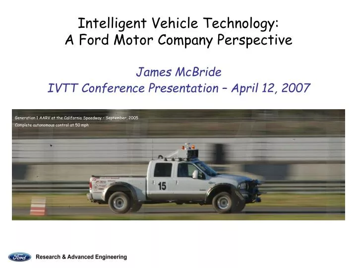
Intelligent Vehicle Technology: A Ford Motor Company Perspective James McBride IVTT Conference Presentation – April 12, 2007. Generation 1 AARV at the California Speedway – September, 2005 Complete autonomous control at 50 mph. A Few Up-front Apologies..!.

E N D
Intelligent Vehicle Technology:A Ford Motor Company PerspectiveJames McBride IVTT Conference Presentation – April 12, 2007 Generation 1 AARV at the California Speedway – September, 2005 Complete autonomous control at 50 mph
A Few Up-front Apologies..! • A great deal of credit is due to colleagues at Ford, the IVS team, our suppliers, and university and government research collaborators. Unfortunately, they cannot all be here to share in the presentation. • My native computer resolution is 1920 x 1200 pixels, which cannot be supported by the conference projector; however, I would be happy to show interested parties more images at the end of the session. • Similarly, some of the sample data I’ll be showing nominally runs on LINUX, capturing in excess of 1,000,000 points/s, so the laptop rendering in Windows doesn’t quite keep up.
What exactly is the “Accident Avoidance Research Vehicle”..?! How does autonomous driving benefit Ford Research and its customers? • Solving the complex challenges required to make a vehicle capable of autonomous driving enables and accelerates the development of technologies which will be found on future automotive Active Safety systems throughout the industry. • The AARV is a versatile platform for evaluating innovative designs in sensors, computational algorithms, and by-wire vehicle control and actuation systems (sense, think, act). • Capable of safely performing completely autonomous driving behaviors and tasks in real-world scenarios.
What Motivates our Research? Unpleasant events can happen if the driver loses control of the vehicle, departs the roadway and/or strikes an obstacle.
Distribution of Light Vehicle Crashes by Type It has been estimated that as much as 40% of these crash scenarios are presently not well covered by emerging near to mid-term automotive safety technologies. From “Thirty-Crash Typology for Vehicle Safety Research”, Volpe National Transportation Systems Center, Project Memorandum, DOT-VNTSC-NHTSA-04-02, September, 2004.
What’s the Annual Impact to Society?! • 43,000 deaths • 2.7 million injuries • $230 billion in economic costs From NHTSA, Traffic Safety Facts, 2005 Statistics
What Conclusions do We Draw? • There is ample room for improvements in automotive safety • Active safety will ultimately lead the way • Autonomous vehicle research will be a key enabler for future active safety technologies
AARV History • March 2004: Active Safety sends volunteers to participate at the 1st DARPA Grand Challenge, network with race teams, establish contacts in the robotics community, learn about the state of the art of autonomous ground vehicle operations • December 2004: based upon design requirements, take delivery of two King Ranch, crew cab, F250s for use as AARV platforms • May 2005: AARV performs first autonomous behaviors, such as GPS waypoint following and static obstacle avoidance • October 2005: AARV is utilized by IVST team (Ford, Delphi, Honeywell, PercepTek venture) to compete in the Finals of the 2nd DARPA Grand Challenge (Mojave Desert) • March 2006: Intelligent Vehicle Systems (IVS) partnership (Ford, Delphi, Honeywell) is formed to conduct collaborative research in autonomous ground vehicle technology and to compete in the 3rd DARPA Grand Challenge (urban driving) • August 2006: IVS is among a very select group of teams to be awarded $1M in matching research funds from DARPA • April 2007: 2nd generation AARV modifications complete on the first of two platforms, autonomous testing underway
Generation 1 AARV Sensor Configuration Generation 1 AARV at the 2005 DARPA Grand Challenge Finals Complete autonomous control through rough Mojave Desert terrain
Velodyne LIDAR MobilEye Vision Cybernet Vision Delphi ACC3 Radars Delphi BUA Radars Riegl LIDARs Generation 2 AARV Sensor Coverage for typical intersection scenario
Present AARV Hardware Capabilities • Drive-by-wire: all systems - throttle, brakes (incl. parking), steering, transmission, redundant mechanical and remote wireless E-Stop systems, etc. We can easily transition from human-controlled, street-legal to fully autonomous operation by the flip of a switch. • Navigation system: state-of-the art decimeter-accuracy localization utilizing GPS/IMU with added state estimators such as wheel speed and vision odometry, SLAM (simultaneous localization and mapping). This ensures less than 1m positional drift per km driven even in extended regions of denied GPS availability. • Sensing suite: generates a 3D map of the world 360° around the vehicle using precision LIDAR, wide FOV radars and vision systems. Includes 8 long-range ACC3 and 4 short-range, dual-beam BUA radars (Delphi), 2 long-range, high-speed, single-line scan (Riegl) and 1 near-range, 64-beam rotating (Velodyne) LIDARS, 2 independent vision systems: radar-fused (MobilEye) and stand-alone (Cybernet). • Computing cluster: processes raw sensor data, plans traversable routes, and actuates and executes fully autonomous driving tasks. Includes 5 Xeon dual core servers (LINUX), 4 P4-class computers (XPC), and 1 AutoBox (high power PC). • Platform: shock isolation and environmental containment for sensors and computers, body armor for vehicle protection, high electrical power generation, modular roof rack for sensor optimization. Vibrations greater than 5Hz rejected, computers and electronics sealed in self-contained and independently air conditioned box, roo-bars and skid plates guard critical vehicle parts, 7KW generated from dual alternator system – 3KW clean 120V AC converted.
Review of Generation 1 AARV Behaviors Navigation and guidance by GPS aided INS Lane-level waypoint following High-speed, by-wire vehicle actuation and control Obstacle avoidance using LIDAR, radar and vision Generation 1 AARV at the 2005 DARPA Qualifier Event Avoiding an in-path obstacle utilizing radar sensing [Video clip NQE Run (4:14)]
Review of Generation 1 AARV BehaviorsCoping with conflicting inputs from multiple sensing modalities Radar sees in-path power lines, LIDAR and vision lose the road cresting the hill, while navigation argues for a different direction… what happens? When competing behaviors arose from multiple sensing modalities, a system “arbiter” used weighted inputs from the various sensors to decide which to trust at any given time. With the exception of a few cases, this approach worked reasonably well. In this example, road and edge detection and tracking were dominant behaviors at the beginning, while GPS navigation governed later on. Road and edge detection was accomplished using vision algorithms (pattern matching, contrasts in color and texture) and LIDAR (sequential single-beam laser scans create a terrain map along the road, looking for flat spots and edges). Speed control was based upon road curvature and roughness, presence of obstacles, and map-based imposed speed limits. [Video clip Mojave Practice Run (2:05)]
Key Differences Between Generation 1 & 2 AARV Capabilities • Evolve from static world to dynamic world capabilities. • Progress from low/no traffic density to urban driving. • Upgraded sensing and computational capabilities for generation of a dense 3D range map of objects surrounding the vehicle: • 360° Field of View • Moving objects (cars, pedestrians, etc.) • Perform complex path planning in real time with moving targets • Change in path planning philosophy, from arbitration-based decision making to fusing the multiple sensing modalities in a single Earth-frame global map. • Add state estimators to navigation system: • Odometry (and other algorithms such as SLAM) based upon wheel speeds, vision and LIDAR data, can assure positional accuracy in regions of denied-GPS availability. • Enables long term affordability (MEMS IMU). • Enables 2nd generation V-V and V-I communication-based features.
Intelligent Vehicle Systems (IVS) Collaboration Delphi, Ford, Honeywell (Ford Subcontractors – Velodyne, University of Michigan, Cybernet)
LIDAR Primer LIDAR (Laser Imaging Detection and Ranging) is an optical remote sensing technology which measures properties of scattered light to determine range and/or other information about a distant target. Like radar, which uses radio waves, the range to an object is determined by measuring the time delay between transmission of a pulse and detection of the reflected signal. The primary difference is that with lidar, much shorter wavelengths of the electromagnetic spectrum are used, typically in the ultraviolet, visible or near infrared, making it possible to image much smaller features (1000x). The LIDAR suite on the XAV-250: 2 high power, fine angular resolution, single-line scanners (Riegl LMS-Q120) 1 360° FOV, 64-beam rotating scanner (Velodyne HD-64E)
Scanning LIDAR Technology Evolution SICK Industrial (indoor) single-line scanner: 100°-180° FOV, 0.50°-1.00° azimuth step size, 30m range, 10cm accuracy, 1000 pts/s, 5Hz serial output Riegl Airborne (outdoor) single-line scanner: 80° FOV, 0.02° azimuth step size, 100m range, 5cm accuracy, 10,000 pts/s, 20Hz Ethernet output DGC2 “multiple-line” scanner: Indiana University Robotics (and various other entrants) fused up to a dozen line scans from multiple SICKs, low resolution, poor data fusion Velodyne DGC2 rotating 64-beam scanner: 360° FOV (azimuth), 20° FOV (elevation) 0.15° azimuth step size, 50m range, 5cm accuracy, 1,000,000 pts/s, 10Hz (8 segment interlaced) Ethernet output, no software tools Velodyne HD-64E production rotating 64-beam scanner: 360° FOV (azimuth), 26.5° FOV (elevation), 0.09° azimuth step size, 80m range, 5mm accuracy, 1,00,000 pts/s, 10Hz Ethernet output, data acquisition and visualization
Dynamic High Definition LIDAR Processing Exit PowerPoint to Run Velodyne DSR (Digital Sensor Recorder) Demonstration
Dynamic High Definition LIDAR Processing [Video clip ParticleView (0:53)]
Truck 1 Hardware Build Truck 1 Sensor Installation Truck 2 Sensor Installation Truck 2 Hardware Build DARPA Site Visit DARPA Final Event V1 Software Field Testing Trip 1 Field Testing Trip 2 DARPA Qualifier Technical Paper V2 Software Final Report DARPA Urban Challenge Key Events Timeline 2007
the first fully autonomous passing operation of two robotic vehicles “pedestrian avoidance” an unexpected in-path obstacle led to a failure mode with the sensor arbitration Generation 1 AARV Extras [Video clips Axion Pass (0:54) & Photographer (0:27)]