Download
1 / 1
10 likes | 121 Views
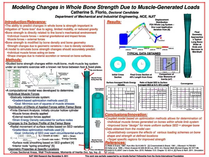
Modeling Changes in Whole Bone Strength Due to Muscle-Generated Loads. Catherine S. Florio, Doctoral Candidate Department of Mechanical and Industrial Engineering, NCE, NJIT. Displacement Distribution FEA Whole Leg System – One Load Application Iteration from [6]. Final Geometry

E N D
Modeling Changes in Whole Bone Strength Due to Muscle-Generated Loads Catherine S. Florio,Doctoral Candidate Department of Mechanical and Industrial Engineering, NCE, NJIT Displacement Distribution FEA Whole Leg System – One Load Application Iteration from [6] Final Geometry Approaches a Typical Long Bone: Wider at Ends and Narrower in Mid-Shaft TYPICAL DATA OBTAINED 6% Improvement Hip Joint Moment Radial Variation of Load Direction 4 Comparison of Polar Moments of Inertia (m4) Initial Cross Section Final Cross Section at 45% Length from Knee 5 6 Net Resultant Force Tibia Femur Muscle Forces Acting Near Hip 7 3 1 8 System Boundary Typical Applied Joint Moment 9 2 Foot Rigid, Fixed Plate Surface Averaged Strain Energy Density Ratio of Nodal SED to Surface Averaged SED at X=Y, 45% Length Torso Fixed to Table Convergence Femur Strength Studied Based on experimental study in [1] Typical Region of Applied Muscle Force Gi = Growth at node i SED = Strain Energy Density ai = Growth rate node i Muscle Forces Acting Near Knee Knee Joint Moment • Introduction/Relevance: • The ability to predict changes in whole bone is strength important in mitigation of “bone loss” due to aging, limited mobility, or reduced gravity • Bone strength is directly related to the bone’s mechanical environment • Individual muscle forces + external gravitational and impact forces • Muscle forces > external forces • Bone strength is modified by bone density and bone geometry • Strength changes due to geometric variations > due to density variations • A model to simulate bone strength changes should accurately predict: • Individual muscle forces acting on bone • Shape changes due to material accretion or removal on bone surfaces Results: • Methods: • Studied bone strength changes within multi-bone, multi-muscle leg system under an isometric exercise with a known net force between foot & fixed plate. • A computational model was developed to determine: • Individual Muscle Forces • Statically indeterminate system: • Gradient-based optimization methods used [2] • Goal: Minimize sum of squares of muscle stresses • Distribution of Effects of Applied Forces within Femur Bone • Finite Element Analysis: Initially circular hollow cylinder • Muscle forces directly applied • External reaction forces applied • Strain Energy Density calculated for surface nodes • Changes to the Surface Profile of the Femur Bone • Radial movement of surface nodes based on SED variation • Gradientless optimization methods used [3] • Goal: Uniformity of SED over each circumferential surface • Surface node smoothing based on SED gradient [4] • Interior node “spring smoothing” [5] • Geometric Properties at Specific Locations • Cross Sectional Areas, Wall Thicknesses, Moments of Inertia (Ixx, Iyy, Ixy, J) • Conclusions/Innovation: • Coupled model based on optimization methods allows for determination of: • Individual muscle forces generated on bones within whole limb system • Improved bone “design” for more uniform surface SED = stronger bone • Data obtained from the model can: • Quantitatively compare the effects of various loading schemes on bone shape and strength at defined locations • Target specific regions for improved strength References:[1] Wells & Evans. 1987. Hum Mov Sci 6:349-72 [2] Crowninshield & Brand. 1981. J Biomech 14:793-801 [3] Heller et al. 1999. J Strain Analysis 34:326-36 [4] Luo. 2010. Int J Numer Meth Biomed Engng. 26:1077-86. [5] ANSYS FLUENT User’s Guide. Nov. 2010. Release 13.0. Chapter 12. 631-4. [6] Florio & Narh. 2011. Simulation 87: 313-33. NJIT GSA Research Day November 9, 2011 This work was partially supported by an Amelia Earhart Fellowship from the Zonta International Foundation