html5-img
1 / 0

Circuit Theory

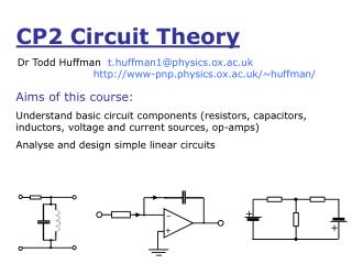
+. –. +. +. Dr Todd Huffman. What is circuit theory? Analysing (electrical) circuits, applying basic rules (Ohm’s law, Kirchoff’s law) to networks of components, to calculate the current and voltage at any point. Circuit Theory. To do this:. You need to know the basic rules.

kaori
Download Presentation

Circuit Theory

An Image/Link below is provided (as is) to download presentation Download Policy: Content on the Website is provided to you AS IS for your information and personal use and may not be sold / licensed / shared on other websites without getting consent from its author. Content is provided to you AS IS for your information and personal use only. Download presentation by click this link. While downloading, if for some reason you are not able to download a presentation, the publisher may have deleted the file from their server. During download, if you can't get a presentation, the file might be deleted by the publisher.

E N D

Presentation Transcript


  1. + – + + Dr Todd Huffman What is circuit theory? Analysing (electrical) circuits, applying basic rules (Ohm’s law, Kirchoff’s law) to networks of components, to calculate the current and voltage at any point

    Circuit Theory

  2. To do this: You need to know the basic rules. Ohm’s Law Current law (Conservation of Charge) Voltage law (Conservation of Energy) And you need to know the techniques Mesh analysis Node analysis And I need to show you some tricks And You need to practice, as with any skill.
  3. Ohm’s law Resistor symbols: Voltage difference  current L I R A V R=Resistance Ω[ohms]
  4. Other Circuit Symbols Sources of Electrical Power Passive Devices or V0 I0 Capacitor Direction of Current or+/- Terminals must be shown. Inductor Ground – Reference Potential V ≡ Zero volts (by definition)
  5. Passive Sign Convention Passive devices ONLY - Learn it; Live it; Love it! R=Resistance Ω[ohms] Two deceptively Simple questions: Which way does the current flow, left or right? Voltage has a ‘+’ side and a ‘-’ side (you can see it on a battery)on which side should we put the ‘+’? On the left or the right? Given V=IR, does it matter which sides for V or whichdirection for I? Explain on white board – Trick
  6. Kirchoff’s Laws I Kirchoff’s current law: Sum of all currents at a node is zero I1 I2 I1+I2–I3–I4=0 I3 I4 (conservation of charge) Passive Sign Convention: If you follow it, you can arbitrarily choose whether “incoming” or “outgoing” currents are Positive at each node independently from all other nodes!
  7. II Kirchoff’s voltage law: Around a closed loop the net change of potential is zero R1 -V0+IR1+IR2+IR3=0 1kΩ I V0 R2 3kΩ 5V Calculate the voltage across R2 4kΩ 5V=I(1+3+4)kΩ R3 Passive Sign Convention really helps!!! Notice “I” VR2=62.5mA×3kΩ=1.9V
  8. R1=1kΩR2=2kΩR3=4kΩ R1 VX? R3 + + I2 10V R2 I1 Solve example on white board Let us use these rules to find Vx. This technique is called “mesh analysis”. Start by labelling currents and using KVL. Then apply KCL at nodes. If you then use Passive Sign Convention, the direction you chose for the currents DOES NOT MATTER!
  9. R1=6kΩR2=2kΩR3=0.5kΩR4=2kΩ VX? R1 R3 10mA + 10V R2 R4 You might think, up to now, that Passive Sign convention is a bit silly. OK…So which is the “right” direction for Vxnow? What if we had a circuit with 5 loops and an additional current source? Let’s solve this circuit and find out what Vx is.
  10. Capacitors Unit – “Farad” C = eA/d Capacitors are also PASSIVE – They too have a kind of “ohm’s law” thatrelates voltage and current. + ++ ++ – – – – – Q=CV
  11. RC circuits 1 Initially VR=0 VC=0 2 R Switch in Position “1” for a long time.Then instantly flips at time t = 0. Capacitor has a derivative! How do we analyze this? There are some tricks… + + 1 V0 I + C ALWAYS start by asking these three questions: 1.) What does the Circuit do up until the switch flips? (Switch has been at pos. 1 for a VERY long time. easy) 2). What does the circuit do a VERY long time AFTER the switch flips? (easy) 3). What can we say about the INSTANT after switch flips? (easy if you know trick)
  12. The Trick!! Remember  Suppose the voltage on a 1 farad Capacitor changes by 1 volt in 1 second. What is the current? What if the same change in V happens in 1 microsecond? So…What if the same change in V happens instantly? Rule: It is impossible to change the voltage on a capacitor instantly! Another way to say it: The voltage at t = 0-e is the same as at t = 0+e.
  13. RC circuits 1 Initially at t = 0-VR=0 VC=0 I=0 2 R + 1 V0 I C Then at t = 0+Must be that VC=0 If VC=0 then KVL says VR=V0 and I=V0/R.Capacitor is acting like a short-circuit. 2 differentiate wrt t Finally at t = +∞VR=0 VC=V0 I=0
  14. R + V0
  15. R1 VX(t)? + 9V R2 C Switch Closes at time t=0. What is the voltage VX as a function of time? R1=R2 R1=2R2 Work it out with student’s help.
  16. Inductance I L for solenoidUnit – “Henry” Inductors are also PASSIVE – They too have a kind of “ohm’s law” thatrelates voltage and current. How should the inductor’s voltage be labelled in the above diagram?
  17. RL circuits Initially t=0-VR=V0 VL=0 I=V0/R 2 R + 1 V0 I L 20R This one is going to be fun, I promise! 1.) What does the Circuit do up until the switch flips? (Switch has been at pos. 2 for a VERY long time. easy) 2). What does the circuit do a VERY long time AFTER the switch flips? (easy) 3). What can we say about the INSTANT the switch flips? (easy if you know trick)
  18. RL circuits Initially t=0-VR=V0 VL=0 I=V0/R 2 R + + 1 + V0 I L 20R + And at t=∞ (Pos. “1”)VR=0 VL=0 I=0 What about at t=0+? A TRICK!
  19. The Next Trick!! Remember  Suppose the current on a 1 henry Capacitor changes by 1 amp in 1 second. What is the voltage? What if the same change in I happens in 1 microsecond? So…What if the same change in I happens instantly? Rule: It is impossible to change the current on an inductor instantly! Another way to say it: The current at t = 0-e is the same as at t = 0+e. Does all this seem familiar? It is the concept of “duality”.
  20. Initially t=0-VR=V0 VL=0 I=V0/R RL circuits 2 R + + + 1 V0 At t=0+ Current in L MUST be the sameI=V0/R So… VR=V0 VR20=20V0and VL = -21V0 !!! I L 20R + For times t > 0 And at t=∞ (Pos. “1”)VR=0 VL=0 I=0
  21. R + V0 L Notice Difference in Scale!
  22. I2 R2 + V0 L R1 t<0 switch closed I2=? t=0 switch opened t>0 I2(t)=? voltage across R1=? Write this problem down and DO attempt it at home
  23. LC circuit Position shown @ t=0+ + V0 L I=I0for t=0 C Return to white board
  24. Initial conditions? I(0)=I0 = ?
  25. LCR circuit R + V0 L I(t)=0 for t<0 V(t) C
  26. Initial conditions? I(0) R=6ΩL=1H C=0.2F
  27. LCR circuit
  28. t LCR circuit
More Related