Download
1 / 26
290 likes | 789 Views
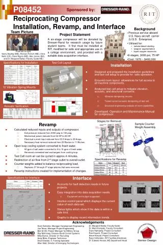
151903 - Fluid Power Engineering. Reciprocating Air Compressor. Prepared by Prof. Jagdish S. Talpada. Lecture - 1. Reciprocating/Positive Displacement Compressors. Gas compression has been one of the anchor points of the industrial revolution ,

E N D
151903 - Fluid Power Engineering Reciprocating Air Compressor Prepared by Prof. Jagdish S. Talpada
Lecture - 1 prepared by Prof. Jagdish S. Talpada
Reciprocating/Positive Displacement Compressors Gas compression has been one of the anchor points of the industrial revolution, beginning with low pressure air supply for iron and steel refining, through higher pressure air supply for drilling and plant operating equipment, to high pressures as required for chemical synthesis, storage and pipeline deliveries of fuel gases. The positive displacement compressors in use today can trace their ancestry back to the original pumping machines invented by James Watts, or the bellows and blowers of blacksmiths. Piston type compressors have a solid position in this field: the technology is mature (more than a century of development), the fabrication process is straight forward, and the equipment is extremely scalable, ranging from miniature emergency tire inflation pumps to compressors of 10,000 horsepower or more. These latter are particularly used in the chemical process and gas transmission industries. There the requirements for high reliability, extreme range in throughput volume, and flexibility in operating pressures make an excellent fit for reciprocating piston compressors. This module describes the operating characteristics of various positive displacement compressors and develops the theory, basic calculations and rudiments of control for the piston type reciprocating compression process. While some references are to the gas compression and transmission industry, the same equipment construction and control methods are used in process compressors for industries such as petrochemicals and chemical synthesis. prepared by Prof. Jagdish S. Talpada
Parts Piston (Reciprocating) The reciprocating piston compressor is the most widely used equipment for gas service. The basic design consists of a piston in a cylinder with pressure actuated check valves to control suction and discharge flow through the cylinder. Standard practice is to have the piston driven by a rod passing through a packing case to seal against pressure leaks. With this double acting design, gas can be compressed on both sides of the piston. The basic design is more than a hundred years old, and is well developed. The throughput and loading can be adjusted by speed variation, addition of clearance to the cylinders, deactivating cylinders to reduce displacement or active control of valve closing, which effectively gives variable control of displacement. Efficiencies of this type of compressor can be more than 85 percent for conversion of horsepower input to pressure rise. Vane A vane compressor consists of a cylindrical chamber with a rotating paddle wheel type drum mounted off center in the chamber. As the drum rotates, the sliding paddle wheel vanes section off volumes, which decrease in volume as they move toward discharge. A suction port is machined into the area where the chambers have the highest volume, and a discharge port is located where the chambers have the smallest volume. Gas enters at the higher volume and is compressed and discharged at the minimum volume. This type of compressor will tolerate more dirt than a reciprocating unit, and is often used for natural gas production services. The maximum differential is limited by the strength of the paddle wheel seals, so these units are not applicable for high pressures and differentials. prepared by Prof. Jagdish S. Talpada
Blower (Rotary) In this compressor, two intermeshing elements rotate in an ellipsoidal chamber with intake and exhaust ports on opposite sides. As they rotate, gas is trapped in spaces formed between the chamber and moved to the opposite side of the chamber, where it is delivered to the discharge. This action is similar to the vane compressor, but is even more tolerant of liquids and dirt. For high pressure ratios, oil may be injected into the suction to improve the seal of the rotors and remove some of the heat of compression. Screw(Rotary) The operation of a screw compressor is similar to the blower, except that the compression chambers are formed between two intermeshed elements similar to worm gears or screw threads. This compressor also requires oil injection for sealing and cooling. It is designed for high pressure ratios but is usually limited to discharge pressures below 250 Psig. prepared by Prof. Jagdish S. Talpada
Cylinder and Ends The compressor cylinder is a casting or forging designed to safely contain some maximum working pressure. It is machined to hold compressor valves and to direct gas flow to and from the cylinder cavity. In combination with the cylinder ends, it must contain the gas pressure, while having sufficiently large gas flow passages so there are minimal pressure drops due to gas flow. The cylinder and ends may also have water passages to stabilize temperature and dimensional changes. All these requirements involve compromises between size, strength, and flow passage size (efficiency). Compressor cylinders are designed for some operating range and service. If conditions change, they may not perform reliably or efficiently. As an example, a cylinder for gas transmission has large flow passages and valve areas for efficiency at high gas volumes and low pressure ratios, and will not function at high ratios. Similarly, a process cylinder may be a forging with small passages, giving higher strength but low efficiency. Piston/Rings The compressor piston converts the energy/work supplied by the engine, applying it to the gas to raise its pressure. The piston must be strong enough to withstand the pressures and forces applied, but still be as light as possible, to minimize reciprocating weights and the resulting shaking forces. The compressor rings seal gas pressure to avoid leaking from one side of the piston to the other. The piston may also be fitted with a rider band, which is a low friction material to keep the metal piston from contacting the bore of the cylinder and causing scuffing and wear. Material for the rings and rider bands is selected to give long life and minimal wear with the typical pressures and gas composition of the compressor. While this is generally a low friction thermoplastic type material, rings may be made of bronze or other materials when temperatures are a problem. prepared by Prof. Jagdish S. Talpada
Valves Compressor valves are simply fast acting check valves with a low pressure drop. They must be optimized to balance the opposing demands for long operating life and minimal pressure drop/flow losses. They may also have special features such as center ports to allow cylinder unloading. The compressor valve is possibly the most critical component when determining the requirements for a compressor service. The flow area is sensitive, as too small an area will give low efficiency, but too large an area can result in valve flutter and early failure. Similarly, valve components must be designed for the expected pressure and temperature conditions. Valves have been designed with many configurations, particularly in the sealing elements. These have progressed through steel, Bakelite, glass filled Teflon or Nylon, and high strength plastics. The most popular designs for sealing elements are ring shaped strips, mushroom shaped poppets, and straight channel strips. The design of compressor valves includes a number of variations to accommodate cylinder flow and unloading requirements. The simplest is a single deck valve, shown on the left above, where gas flows into passages in one face, across the sealing elements, and out through passages in the back face of the valve. A modification of this design is to have a large opening in the center of the valve. This allows adding a cylinder deactivator or clearance volume to the cylinder. This added feature comes at the expense of reduced flow area and efficiency. To compensate for this, two valves may be assembled together with a flow passage through the center. This double deck valve design has improved flow area and efficiency. This type of valve can only be used in a cylinder designed to accept its increased height. prepared by Prof. Jagdish S. Talpada
Packing The compressor packing is a series of pressure containing rings located in the crank end of a double acting compressor cylinder. These seal against the piston rod and prevent leakage, so that the cylinder can compress gas on both sides of the piston. Again, as with compressor rings, the packing material is selected to provide best life and sealing with expected conditions. The packing is generally pressure lubricated, and may have coolant flow to remove friction heat. There are also various specialty types to reduce gas leakage around the rod. This may be important when compressing highly flammable or toxic gases. It is also becoming more important in reducing gas leakage and emission of “greenhouse gases”. Clearance Unloaders In many applications, the volume of gas to be delivered may change based on either gas supply or process demands. Also, varying pressure conditions can change the load on the driver, requiring load control. This may be accomplished by speed variation, deactivating cylinders or cylinder ends, or by varying cylinder clearance. This last option is highly preferred, as speed control may have a limited range, and deactivating cylinders or ends can cause mechanical shaking or acoustic pulsations. Clearance unloaders allow varying throughput and load with minimal loss of efficiency. Unloaders are not actually a part of a compressor, but are included on many installations, to give load and throughput control. This may be done by volumes cast into the cylinder or heads, with a valve to close the passageway. Other options are valve cap pockets and head end variable pockets. Added clearance may have a simple handwheel to control its operation, or may have pneumatic actuators, which allow automatic operation. prepared by Prof. Jagdish S. Talpada
Distance Piece Compartment(s) A distance piece section may be placed between the crosshead and cylinder to prevent leakage of gas from the compressor packing entering the compressor crankcase. At the crosshead end, an oil seal around the compressor rod prevents oil from migrating to the cylinder, and gas from entering the crankcase. This distance piece is normally vented to remove any gas which leaks from the packing. In cases of explosive or toxic gases there may be two distance pieces in series, to assure containment of the gases. prepared by Prof. Jagdish S. Talpada
Lecture- - 2 prepared by Prof. Jagdish S. Talpada
Definition of Terms Single and Double Acting Compressor A Single Acting piston compresses gas on only one face, either by design or by deactivating valves on one side of a double acting cylinder Double Acting – Piston compresses gas alternately on both faces. Connecting Rod A compressor element connecting the crankshaft to the compressor piston or crosshead. The connecting rod converts the rotation of the crankshaft into linear motion to drive the compressor piston. Crosshead A crosshead is a sliding component at the outer end of the connecting rod, which converts the eccentric motion of the connecting rod to pure linear, eliminating side forces on the compressor piston. prepared by Prof. Jagdish S. Talpada
Wrist Pin/Crosshead Pin The wrist or crosshead pin connects the outer end of a connecting rod to either a single acting, trunk type piston (wrist pin) or to a crosshead (crosshead pin) Compressor Rod/Piston Rod A cylindrical rod which connects the compressor piston to a crosshead, normally passing through a packing case to seal compression pressure into the cylinder Compressor Piston A reciprocating component, normally fitted with piston rings which changes the volume of a cylinder, providing compression. It may be a simple trunk type piston directly connected to the connecting rod, or double acting, driven by a compressor rod. Compressor Rings Compressor rings provide a seal between the compressor piston and cylinder wall, preventing gas leakage either into or out of the cylinder volume. Rider Rings and Rider Bands Rider rings or bands are normally provided on a double acting piston to prevent contact of the piston with the cylinder wall. Rider rings/bands are normally made of carbon filled Teflon or other low friction material. prepared by Prof. Jagdish S. Talpada
Compressor Packing Compressor packing is used in a double acting cylinder to seal around the compressor rod, preventing gas leakage from the cylinder. Packing is normally a series of segmented metallic rings, assembled and held in the end of the cylinder by the packing case. Compressor Valves Compressor valves are high speed check valves, controlling flow of gas into the cylinder (suction valve) or out of the cylinder (discharge valve). They are designed for minimal pressure loss and maximum reliability Cylinder Clearance (Mechanical) Clearance must be provided at the end of the piston stroke to avoid contact between the piston face and the compressor cylinder head. This clearance is expressed in linear measurement (inches or mm.). Cylinder Clearance (Volume) Volumetric clearance is space left at the end of a piston stroke, both due to mechanical clearance and volumes above suction and discharge valves to allow for good gas flow. Clearance may also be added for control of throughput volume and/or load control (unloaders or clearance pockets). prepared by Prof. Jagdish S. Talpada
Compression Ratio Compression ratio is the measure of increase in pressure across a compressor cylinder. It is determined by dividing the discharge pressure by suction pressure (both pressures must be absolute rather than gauge) Pressure – Absolute and Gauge Gauge pressure is the value which would be measured by a gauge calibrated to indicate zero pressure when exposed to atmosphere. Absolute pressure is pressure which would be read from a gauge calibrated to read zero when exposed to complete vacuum. Normally absolute pressure is gauge pressure + 14.73 PSI. prepared by Prof. Jagdish S. Talpada
Lecture - 3 prepared by Prof. Jagdish S. Talpada
Cycle Events In a reciprocating compressor, the process follows four main events – compression, discharge, re-expansion and intake. The first two are accomplished as the piston moves forward, reducing cylinder volume, while the second takes place as the piston moves back down the cylinder. For a more complete picture, assume starting the cycle with the compressor at the bottom of its stroke, with maximum cylinder volume. The cylinder is full of gas at suction pressure, and both suction and discharge valves are closed by gas pressure. As the piston moves forward, the cylinder volume decreases and pressure rises. When the cylinder pressure rises slightly above discharge pressure, the discharge valve opens and gas is pushed into the discharge piping for the rest of the stroke. At top center, the discharge valve closes. As there must be clearance between the piston face and cylinder head to prevent parts hitting each other, some volume of gas is trapped in the cylinder at discharge pressure. As the piston moves back down the cylinder, this gas re-expands until it reaches suction pressure. At this point, the suction valve opens and a fresh charge of gas flows prepared by Prof. Jagdish S. Talpada
Volumetric Efficiency As noted above, the cylinder does not bring gas in through the entire piston travel. The percentage of stroke the suction valve is open, compared to the entire stroke is called “volumetric efficiency”. If there were no clearance (volume) left when the piston completed its compression stroke, then cylinder pressure would immediately drop to suction pressure as the piston returned, giving 100 percent volumetric efficiency. Thus, the cylinder displacement would be equal to the volume delivered with each stroke. However, due to gas re-expansion, the suction valve opening is delayed. This delay becomes greater when the cylinder pressure ratio increases or the clearance volume increases. Thus, the cylinder delivers a reduced volume to the discharge condition. The pictures below illustrate this effect, with the picture on left showing effect of increasing clearance, and on right the effect of increasing pressure ratio. At high pressure ratios, or with large amounts of clearance, the valve opening may be delayed to the point that the valve does not open, and no gas flows through the cylinder. This condition is called zero volumetric efficiency, and can cause serious cylinder heating problems. In normal operation, friction of rings on the cylinder creates heat which is carried away with the gas being compressed. Since at zero volumetric efficiency, no gas is entering or leaving the cylinder, all friction heating effects are contained within the cylinder, causing an uncontrolled temperature rise. As the hot gas is contained within the cylinder, normal temperature detection in the discharge line will not be effective. prepared by Prof. Jagdish S. Talpada
Clearance Control As noted above, cylinder clearance will significantly affect throughput and horsepower of a compressor. Some amount of volumetric clearance is built into the cylinder to prevent the compressor cylinder from contacting the heads at the extremes of piston travel, and to provide a smooth gas flow path into and out of the cylinder. Beyond this, additional clearance can be introduced by providing clearance pockets or passages which open into the cylinder cavity. These have valves which can be opened or closed to add or remove the clearance from the compression process. Also, some cylinders may be equipped with a variable clearance pocket on the outboard cylinder head. These have a piston positioned by a screw and hand wheel, which will add a variable amount of clearance. Work of Cycle The familiar definition of work is force times distance. In the pressure-volume cards shown above, piston movement or change in volume defines a distance. As the force against the piston changes as pressure increases and decreases, the area of the card defines the work involved in the cycle. A key point to note is that for a given pressure differential, changing the volumetric efficiency changes both the volume delivered and the work of the cycle. This is the basis for load control of compressors by changing the cylinder clearance. prepared by Prof. Jagdish S. Talpada
Pressure Ratio Pressure ratio is the discharge pressure of the compressor divided by the suction pressure. These pressures must be in absolute (Psia) rather than gauge (Psig) pressure. As most operating gauges read in Psig, atmospheric pressure must be added. This is normally about 14 Psi. A reciprocating compressor may be able to operate at high pressure ratios, but is usually limited by other conditions, particularly temperature. A compressor’s discharge temperature increases with pressure ratio. For example, at a pressure ratio of four and a suction temperature of 60 degrees, discharge temperature would be about 310 degrees. This is a safe practical limit for most compressor components. Consequently, pressure ratios across any single compressor cylinder rarely are allowed to exceed four to one. Temperature Rise – Ratio Effect When a gas is compressed, its temperature rises in proportion to the pressure ratio. For low pressure ratios, the discharge temperature may be only twenty to prepared by Prof. Jagdish S. Talpada
fifty degrees higher than suction temperature. When the pressure ratio is high, such as on storage or production service, the discharge temperature may be more than a hundred degrees higher than the suction. This is true for all types of compressors. This temperature rise may limit the amount of pressure rise allowable across a compressor, or require special components to withstand the temperature. This temperature must be reduced before gas is put into underground pipelines, to prevent melting their protective coatings. In most cases, the discharge temperature from a compressor station must be kept below 1250F, requiring gas coolers at higher pressure ratios. This is particularly the case at storage and production stations, where high pressure ratios give extreme discharge temperatures. prepared by Prof. Jagdish S. Talpada
Lecture - 4 prepared by Prof. Jagdish S. Talpada
Multi-Staging Sharing Differential The limits of operation listed above show that a reciprocating compressor has a number of mechanical limits, most of which are related to pressure differential. Often differentials are required greater than can be accomplished with a single stage of compression. In this case, it is necessary to have multiple stages of compression. This is accomplished by having a cylinder or cylinders which take gas in at a low pressure, compress and discharge to an intermediate pressure, then repeat with additional cylinders to take the gas to the discharge pressure. In this process, pressure differential and temperature rise across each cylinder can be controlled to a reasonable level. The gas may be cooled between stages to minimize discharge temperatures. Normally this is done with two or more cylinders on the same compressor unit, with gas cooling between stages. prepared by Prof. Jagdish S. Talpada
Efficiency Increase When gas is compressed, the temperature rise effectively creates higher volume at the discharge conditions. This requires more energy (work) for compression. In multiple stage compression with cooling, the temperature rise is minimized, which reduces the total work required to compress to the final discharge. Operating Difficulties Multiple stage compression presents challenges for both design and operation. At the design stage, cylinders must be sized so that all stages are operating within their limits. In operation, the pressure balance between stages must be maintained by following a specified unloading sequence when pressures change, or when controlling engine load. Mechanical failures such as leaking compressor valves or rings can cause pressure unbalance, which may put excessive differentials or temperatures on other stages. The compressor piping and pulsation bottles will also be more complex, which will probably require an electric analog or digital evaluation to avoid pulsation or vibration problems. prepared by Prof. Jagdish S. Talpada