Download
1 / 32
330 likes | 458 Views
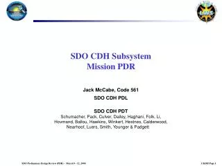
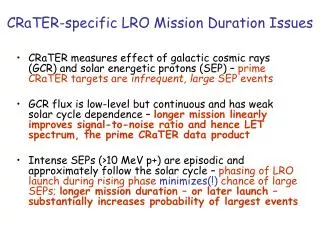
Shackleton Crater Reconnaissance Mission PDR. Trevor Fedie Jason Breeggemann Brian Evans Mike Gavanda Matt Gildner Jeromie Hamann Brian Nackerud Andrew Smude Jordan Stewart. Project Overview. Image 5 km annular region around Shackleton Crater (at Moon’s south pole) 3 color imagery

E N D
Shackleton Crater Reconnaissance Mission PDR Trevor Fedie Jason Breeggemann Brian Evans Mike Gavanda Matt Gildner Jeromie Hamann Brian Nackerud Andrew Smude Jordan Stewart
Project Overview • Image 5 km annular region around Shackleton Crater (at Moon’s south pole) • 3 color imagery • 10 cm resolution • Image 80% of region in one month • Act as communication relay for lunar lander exploring interior of crater • 2.5 Mbps S-band from lander • Transmit to Earth once per day
Project Overview • Baseline orbit of 30 x 216 km • Period approximately 120 minutes • 12 orbits each day • Spacecraft must fit into Taurus Launch Vehicle • Goal of 445 kg for everyday launch opportunities • Must handle spin stabilized upper stage (60 rpm) • Must interface with launch vehicle upper stage • Must fit into launch vehicle envelope
Mission Profile • Launch using Taurus Launch Vehicle • De-spin, make burn for Earth-Moon transit • Burn to enter Lunar orbit • Begin imaging region around crater • Send data back to Earth once per day • Finish imaging crater in about 14 days • Lunar lander operations begin 4 months after launch and last for one year
Spacecraft Data Flow Star Tracker Reaction Wheels Flight Computer Gyroscope Rocket Motor SSR Thrusters Transponders Camera Antennas Temp Sensors
Camera Crater Imaging Strategy (Note: not to scale)
Camera • HiRISE (used on Mars Reconnaissance Orbiter) • Pushbroom TDI imager (4,048 pixels across swath) • 0.5 m aperture • 28 Gbits internal data storage • Internal LUT image compression • Mass: 65 kg • Average power: 60 W
Computing & Data Storage 3U Compact PCI PowerPC RAD750 Enhanced Power PCI Bridge SSR P9 family 160 Gbits BOL Built-in FELICS 256 Mb SDRAM
Communications • Earth Comm. • Cassegrain Antenna • D=.98m • d=0.3m • Power usage 40 W • Double reflection
Earth Communications Transmit high resolution photos Only one contact with White Sands per day Around 90 Gbits a day in pictures Ka-band 26 Ghz parabolic dish Data rate:100 Mbps Power: 40 W Gain: 44 db White Sands receiving: 45 db/T Similar to LRO
Rover Communications • Relay for rover in crater • Required data rate of 2.5 Mbs • Required S-band from rover • 2.3 Ghz Omni-directional transmitter • Power: 5 W • Gain: 5 db • Rover Gain: 5 db • L3 T&C transceiver MSX-765 • Store Data onboard satellite until downlink to White Sands ground Station
Communications • Earth • 4230 sec average daily window • Tracking • Azimuth: 0.01617 deg/s • Elevation: 0.0154 deg/s • Moon • 12 communication windows • 6.533 min over crater • 117.6 Gbits of data a day • 2 min required to send to earth
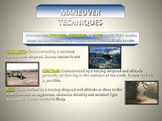
Attitude Determination and Control • Pointing stability/accuracy • Torque disturbances must result in 10 cm or less ground displacements during exposure time • Attitude accuracy -Roll axis <2.5 arcmin -Pitch axis <8.6 arcmin -Yaw axis <2.7 arcmin • Maneuverability • 3-axis control • Pointing reassignment as fast as 90 deg in 6 minutes
Attitude Determination and Control • SED 16 Autonomous Star Tracker by Sodern • 36 arcsec in pitch/yaw, 108 arcsec roll (bias plus noise) • 10 Hz update • 25x25 deg field of view • Mass: 2.9 kg (with Baffle) • Average power: 10.7 W
Attitude Determination and Control • Scalable SIRU (gyro) by Northrop Grumman • Achieves Gyro Bias stability of 0.0003 deg/hr • Four HRGs (Hemispherical Resonator Gyro), with associated loop control/readout/thermal control electronics, and sensing along the octahedral-tetrad axes • Low noise • Mass: 7.1 kg • Average power: 38 W
Attitude Determination and Control • Momentum build up •Disturbance Torques - Gravity gradients - Solar pressure - Internal - Deployables •Slewing Maneuvers - Minimum twice a day • HR14 Constellation Series Reaction Wheels by Honeywell • Max Reaction Torque 0.2 N-m • Momentum Capacity 50 N-m-s • Mass: 8.5 kg
Propulsion System Rocket Motor: -EADS Astrium S400-12 -MMH/MON-1 -420N Isp:318s -Total V needed: 1011m/s
Propulsion System • Twelve 4N thrusters • MMH/MON-1 Fuel/Oxidizer • EADS Astrium S4 • Two 0.05 cubic meter tanks • Composite structure • 3600 psi rated • Lincoln Composites
Determination of Thermal Environment • Moon surface temp • Altitude and attitude • Lunar view factor • Intense reflected IR from lunar surface. • Thus objects placement will important • If thermo enviroment is compromised anywhere and active system will be used
Thermal Analysis • Equilibrium temperature range of 270-310 Kelvin • Electric heaters and sensors on items that do not fall within their ideal ranges. • Use of heat tubes and radiators if needed • Will be tuned in by a dynamic model
Structural System Determination • Properties of Ti an Al • Bulk system of TI. • AL only used where conduction requires it. • Current structural mass of approximately 18Kg. • Titanium will also have less thermal expansion
Radiation Protection Everything placed into space must be protected in some way from cosmic radiation. Typical commercial satellites protected to 2Mrad for a 10 year mission and SF of 2. Our mission is shorter. Everything will be shielded to 1Mrad, unless otherwise required by specific components. 3g/cm2 of Al will provide an order of magnitude reduction in total dosage over a 10 year mission: this is sufficient to reduce total dosage to less than 1 Mrad. Sensitive components shall be organized as to benefit from spot-shielding. This layout must also mesh with the thermal management system.
Radiation Protection Reduction in Exposure when utilizing Al shielding *Courtesy of http://see.msfc.nasa.gov/ire/iretech.htm
Power • Requirements • Supply power to satellite • Support mission profile and requirements • Major Design Drivers • Must fit inside Taurus launch vehicle • Provide adequate power • Reliable and easy to obtain
Power • Trade Studies • Solar Power vs. RTG vs. Nuclear Reactor • Silicon vs. GaAs solar cells • Body Mounted Array vs. Gimbaled Array Panels
Power Triple Junction GaAs Solar Cells 28.5% average efficiency 26.6 square cm Radiation Resistant 289 Watts per square meter Secondary Batteries Peak Power Trackers Active power regulation Protects sensitive electrical components
Power SolarArray Battery PeakPowerTracker ChargeController DischargeController 28V Bus Loads
Power - Battery • Lithium Ion • Highest number of Cycles for chosen depth of discharge (DOD) • High energy density • Customizable size and shape
Satellite Structure - Transport Fitting within the Taurus launch vehicle
Rest of Semester • Detailed end-to-end data flow from lander and camera back to Earth including timeline, data rates, use of on-board storage, and contact times • Optimize power system for our mission/components • Detailed design of spacecraft structure and thermal conduction/radiation model • Integrate radiation protection with components and structure