Download
1 / 40
410 likes | 591 Views
LONGITUDINAL DYNAMICS IN PARTICLE ACCELERATORS. by Joël Le DuFF (retired from LAL-IN2P3-CNRS). Cockroft Institute, Spring 200 6. Bibliograph y : O ld Books. M. Stanley Livingston High Energy Accelerators (Interscience Publishers, 1954)

E N D
LONGITUDINAL DYNAMICSIN PARTICLE ACCELERATORS by Joël Le DuFF (retired from LAL-IN2P3-CNRS) Cockroft Institute, Spring 2006
Bibliography: Old Books • M. Stanley Livingston High Energy Accelerators • (Interscience Publishers, 1954) • J.J. Livingood Principles of cyclic Particle Accelerators • (D. Van Nostrand Co Ltd , 1961) • M. Stanley Livingston and J. B. Blewett Particle Accelerators • (Mc Graw Hill Book Company, Inc 1962) • K.G. Steffen High Energy optics • (Interscience Publisher, J. Wiley & sons, 1965) • H. Bruck Accelerateurs circulaires de particules • (PUF, Paris 1966) • M. Stanley Livingston (editor) The development of High Energy Accelerators • (Dover Publications, Inc, N. Y. 1966) • A.A. Kolomensky & A.W. Lebedev Theory of cyclic Accelerators • (North Holland Publihers Company, Amst. 1966) • E. Persico, E. Ferrari, S.E. Segre Principles of Particles Accelerators • (W.A. Benjamin, Inc. 1968) • P.M. Lapostolle & A.L. Septier Linear Accelerators • (North Holland Publihers Company, Amst. 1970) • A.D. Vlasov Theory of Linear Accelerators • (Programm for scientific translations, Jerusalem 1968)
Bibliography:New Books • M. Conte, W.W. Mac Kay AnIntroduction to the Physics of particle Accelerators • (World Scientific, 1991) • P. J. Bryant and K. Johnsen The Principles of CircularAccelerators and Storage Rings • (Cambridge University Press, 1993) • D. A. Edwards, M. J. Syphers AnIntroduction to the Physics of High Energy Accelerators • (J. Wiley & sons, Inc, 1993) • H. Wiedemann Particle AcceleratorPhysics • (Springer-Verlag, Berlin, 1993) • M. Reiser Theory and Design of Charged Particles Beams • (J. Wiley & sons, 1994) • A. Chao, M. Tigner Handbook of Accelerator Physics and Engineering • (World Scientific 1998) • K. Wille The Physics of Particle Accelerators: An Introduction • (Oxford University Press, 2000) • E.J.N. WilsonAn introduction to Particle Accelerators • (Oxford University Press, 2001) And CERN Accelerator Schools (CAS) Proceedings
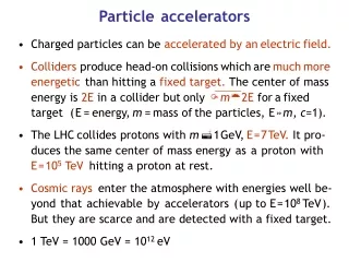
E0 = m0c2 = E0+ W Types of accelerators Total energy = Rest energy + Kinetic energy electron E0=0,511 MeV protons E0=938 MeV
Brief history of accelerators • 1919 Rutherford gets the first nuclear reactions using natural alpha rays • (radio activity) of some MeV). • « He notes already that he will need many MeV to study the atomic nucleus » • 1932 Cockcroft & Walton build a 700 KV electrostatic generator and break • Lithium nucleus with 400 KeV protons. • (Nobel Price in 1951) • 1924 Ising proposes the acceleration using a variable electric field between drift tubes • ( the father of the Linac). • 1928 Wideroe uses Ising principle with an RF generator, 1MHz, 25 kV • and accelerate potassium ions up to 50 keV. • 1929 Lauwrence driven by Wideroe & Ising ideas invents the cyclotron. • 1931 Livingston demonstrates the cyclotron principle by accelerating hydrogen ions • up to 80 KeV.
Brief history of accelerators (2) • 1932 The cyclotron of Lawrence produces protons at 1.25 MeV and « breaks atoms » • a few weeks after Cockcroft & Walton • (Nobel Prize in 1939) • 1923 Wideroe invents the concept of betatron • 1927 Wideroe builds a model of betatron but fails • 1940 Kerst re-invents the betatron which produces 2.2 MeV electrons • 1950 Kerst builds a 300 MeV betatron
Main Characteristics of an Accelerator • ACCELERATION is the main job of an accelerator. • The accelerator provides kinetic energyto charged particles, hence increasing their momentum. • In order to do so, it is necessary to have an electric field , preferably along the direction of the initial momentum. BENDING is generated by a magnetic field perpendicularto the plane of the particle trajectory. The bending radius obeys to the relation : FOCUSING is a second way of using a magnetic field, in which the bending effect is used to bring the particles trajectory closer to the axis, hence to increase the beam density.
Acceleration & Curvature Within the assumption: z x, r s the Newton-Lorentz force: o becomes: leading to:
Energy Gain In relativistic dynamics, energy and momentum satisfy the relation: Hence: The rate of energy gain per unit length of acceleration (along z) is then: and the kinetic energy gained from the field along the z path is: where V is just a potential
Methods of Acceleration 1_ Electrostatic Field Energy gain : W=n.e(V2-V1) limitation : Vgenerator=S Vi Electrostatic accelerator 2_ Radio-frequency Field Synchronism :L=vT/2 v=particle velocity T= RF period Wideroe structure also :
Methods of Acceleration (2) 3_ Acceleration by induction From MAXWELL EQUATIONS : The electric field is derivedfrom a scalar potentialand a vector potentialA The time variation of the magnetic fieldHgenerates an electric fieldE
Electrostatic accelerator Accélérateur colonne d.c. high voltage generator Accelerating column HV system used byCockcroft & Waltonto break the lithiumnucleus
Electrostatic accelerator (2) An insulated belt is used to transport electric charges to a HV terminal . The charges are generated by field effect from a comb on the belt . At the terminal they are extracted in a similar way. The HV is distributed along the column through a resistor. Van de Graaf type electrostatic accelerator
Induction law Newton-Lorentz force A constant trajectory also requires : Betatron The betatron uses a variable magnetic field with time. The pole shaping gives a magnetic field Bo at the location of the trajectory, smaller than the average magnetic field.
Cyclotron At each radius r corresponds a velocity v for the accelerated particle. The half circle corresponds to half a revolution period T/2 and B is constant: The corresponding angular frequency is : Synchronism if : v=Vsint m = m0 (constant) if W << E0 If so the cyclotron is isochronous
Cyclotron (2) Here below the 27-inch cyclotron, Berkeley (1932). The magnet was originally part of the resonant circuit of an RF current generator used in telecommunications. Cyclotron of M.S.Livingstone (1931) On the left the 4-inch vacuum chamber Used to validate the concept. On the right the 11-inch vacuum chamber of the Berkeley cyclotron that produced 1,2 MeV protons. In both cases one single electrode (dee).
Cyclotron (3) Cyclotron SPIRAL at GANIL Here below is an artist view of the spiral shaped poles and the radio-frequency system. Here above is the magnet and its coils SPIRAL accelerates radio-active ions
Cyclotron (4) Cyclotrons at GANIL, Caen
Cyclotron (5) Energy-phase equation: Energy gain at each gap transit: Particle RF phase versus time: where is the azimuthal angle of trajectory Differentiating with respect to time gives: Smooth approximation allows: Relative phase change at ½ revolution And smooth approximation again:
Cyclotron (6) Separating: Integrating: with : Rest energy Injection phase Starting revolution frequency
Microtron (Veksler, 1954) The expression shows that if the mass increases, the frequency decreases : mr Synchronism condition: If the first turn is synchronous : Since required energy gains are large the concept is essentially valid for electrons. electrons 0.511 MeV Energy gain per turn protons 0.938 GeV !!!
Microtron « Racetrack » Allows to increase the energy gain per turn by using several accelerating cavities (ex : linac section) Synchronism is obtained when the energy gain per turn is a multiple of the rest energy: ()/turn = integer Carefull !!!! This is not a « recirculating » linac
The advantage of Resonant Cavities - Considering RF acceleration, it is obvious that when particles get high velocitiesthe drift spaces get longer and one loses on the efficiency. The solution consists of using a higher operating frequency. - The power lost by radiation, due to circulating currents on the electrodes, is proportional to the RF frequency. The solution consistsof enclosingthesystemin a cavitywhich resonant frequency matches the RF generator frequency. • Each such cavity can be independently powered from the RF generator. • - The electromagnetic power is now constrained in the resonant volume. • - Note however that joule losses will occur in the cavity walls (unlessmade of superconducting materials) RF
The Pill Box Cavity From Maxwell’s equations one can derive the wave equations : Solutions for E and H are oscillating modes, at discrete frequencies, of types TM ou TE. For l<2a the most simple mode, TM010, has the lowest frequency ,and has only two field components: Ez H
The Pill Box Cavity (2) • The design of a pill-box cavity can be sophisticated in order to improve its performances: • A nose cone can be introduced in order to concentrate the electric fieldaround the axis, • Round shaping of the corners allows a betterdistribution of the magnetic field on the surface and a reduction of the Joule losses. It also prevent from multipactoring effects. • A good cavity is a cavity which efficiently transforms the RF power into accelerating voltage.
Energy Gain with RF field RF acceleration In this case the electric field is oscillating. So it is for the potential. The energy gain will depend on the RF phase experienced by the particle. Neglecting the transit time in the gap.
Transit Time Factor Oscillating field at frequencyand which amplitude is assumed to be constant all along the gap: Consider a particle passing through the middle of the gap at time t=0 : The total energy gain is: ( 0 < T < 1 )
Transit Time Factor (2) Consider the most general case and make use of complex notations: pis the phase of the particle entering the gap with respect to the RF. Introducing: and considering the phase which yields the maximum energy gain:
Important Parameters of Accelerating Cavities Shunt Impedance Relationship between gap voltage and wall losses. Quality Factor Relationship between stored energy in the volume and dissipated power on the walls. Filling Time Exponential decay of the stored energy due to losses.
Shunt Impedanceand Q Factor The shunt impedance R is definedas the parameterwhich relates the accelerating voltage V in the gap to the powerdissipated in the cavity walls(Joule losses). The Q factor is the parameterwhich comparesthe stored energy, Ws, inside the cavity to the energy dissipated in the walls during an RF period (2/). A high Q is a measure of a good RF efficiency
Filling Time of a SW Cavity From the definition of the Q factor one can see that the energy is dissipatedat a ratewhich is directly proportional to the stored energy: leading to an exponential decay of the stored energy: avec (filling time) Since the stored energy is proportionalto the square of the electric field, the latter decay with a time constant 2 . If the cavity is fed from an RF power source, the stored energy increases as follows:
Equivalent Circuit of a Cavity RF cavity: on the average, the stored energyin the magnetic fieldequal thestored energy in the electric field, Wse=Wsm RLC circuit:the previous statement is true for this circuit, where the electric energy is stored in C and the magnetic energy is stored in L: Leading to:
Input Impedance of a Cavity The circuit impedance as seen from the input is: Within the approximation«0the impedancebecomes: When satisfies the relation Q=0/2 one has Ze= 0,707 |Ze|max , with |Ze|max= R. The quantity 2/0is called the bandwidth (BW) :
Loaded Q If R representsthe losses of the equivalent resonant circuitof the cavity, then the Qfactor is generally called Q0. Introducing additional losses, for instance through a coupling loopconnected to an external load, corresponding to a parallel resistor RL,then the total Q factor becomes Ql( loaded Q ): Defining an external Q as, Qe=RL/0L, one gets:
Principle of Phase Stability Let’s consider a succession of accelerating gaps, operating in the 2π mode, for which the synchronism condition is fulfilled for a phase s . For a 2π mode, the electric field is the same in all gaps at any given time. is the energy gain in one gap for the particle to reach the next gap with the same RF phase: P1 ,P2, …… are fixed points. If an increase in energy is transferred into an increase in velocity, M1 & N1 will move towards P1(stable), while M2 & N2 will go away from P2 (unstable).
A Consequence of Phase Stability Transverse Instability Longitudinal phase stability means : defocusing RF force The divergence of the field iszero according to Maxwell : External focusing (solenoid, quadrupole) is then necessary
Focusing Accelerating section, of an electron linac, equipped with quadrupoles Accelerating section, of an electron linac, equipped with solenoids
Focusing (2) For protons & ions linacs, small quadrupoles are generally placed inside the drift tubes. Those quadrupoles can be either electro-magnets or permanent magnets.
The Traveling Wave Case The particle travels along with the wave, and k represents the wave propagation factor. If synchronism satisfied: where 0 is the RF phase seen by the particle.
Multi-gaps Accelerating Structures:A- Low Kinetic Energy Linac (protons,ions) Mode 2p L= vT = bl Mode p L= vT/2 In « WIDEROE » structureradiated powerwCV In order to reduce the radiated power the gap is enclosed in a resonant volume at the operating frequency. A common wall can be suppressed if no circulating current in itfor the chosen mode. ALVAREZ structure