Download
1 / 21
210 likes | 268 Views
1. The user clicks on a link to indicate which document is to be retrieved. The browser must determine the address that contains the document. It does this by sending a query to its local name server. 2. 3.

E N D
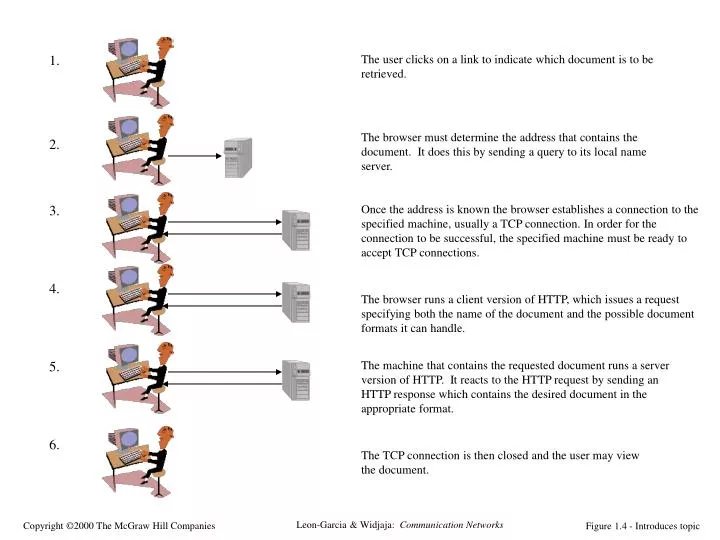
1. The user clicks on a link to indicate which document is to be retrieved. The browser must determine the address that contains the document. It does this by sending a query to its local name server. 2. 3. Once the address is known the browser establishes a connection to the specified machine, usually a TCP connection. In order for the connection to be successful, the specified machine must be ready to accept TCP connections. 4. The browser runs a client version of HTTP, which issues a request specifying both the name of the document and the possible document formats it can handle. 5. The machine that contains the requested document runs a server version of HTTP. It reacts to the HTTP request by sending an HTTP response which contains the desired document in the appropriate format. 6. The TCP connection is then closed and the user may view the document. Figure 1.4 - Introduces topic
Request HTTP server HTTP client Response Figure 2.1
HTTP server HTTP client Ephemeral Port # Port 80 GET 80, # TCP TCP #, 80 STATUS Figure 2.2
n-PDUs n entity n entity Figure 2.3
n+1 entity n+1 entity n-SDU n-SDU n-SAP n-SAP n-SDU H n entity n entity n-SDU H n-PDU Figure 2.4
(a) Segmentation Reassembly n-SDU n-SDU n-PDU n-PDU n-PDU n-PDU n-PDU n-PDU (b) Blocking Unblocking n-SDU n-SDU n-SDU n-SDU n-SDU n-SDU n-PDU n-PDU Figure 2.5
Application A Application B Application Layer Application Layer Presentation Layer Presentation Layer Session Layer Session Layer Transport Layer Transport Layer Communication Network Network Layer Network Layer Network Layer Network Layer Data Link Layer Data Link Layer Data Link Layer Data Link Layer Physical Layer Physical Layer Physical Layer Physical Layer Electrical and/or Optical Signals Figure 2.6
PS = packet switch C = computer C PS C PS PS PS C C C Figure 2.7
G net 3 G net 1 G G G net 5 net 2 net 4 G G = gateway/router Figure 2.8
Application B Application A data Application Layer Application Layer ah data Presentation Layer Presentation Layer ph data Session Layer Session Layer sh data Transport Layer Transport Layer th data Network Layer Network Layer data nh Data Link Layer Data Link Layer dt dh data Physical Layer Physical Layer bits Figure 2.9
Application Layer Application Layer Transport Layer Transport Layer Internet Layer Internet Layer Network Interface Network Interface (b) (a) Figure 2.10
Application Transport Internet Internet Network Interface Network Interface Machine B Machine A Application Transport Router/Gateway Internet Network Interface Network 1 Network 2 Figure 2.11
IP Network Interface 1 Network Interface 3 Network Interface 2 RTP SMTP HTTP DNS TCP UDP Figure 2.12
(1,1) (a) (2,1) (2,2) router s PPP (1,3) r w Ethernet (1,2) (b) Server PC HTTP HTTP TCP Router TCP IP IP IP Net Interface Net Interface Net Interface Ethernet PPP Figure 2.13
IP Header Header contains source and destination physical addresses; network protocol type Frame Check Sequence Ethernet Header Figure 2.14
HTTP Request Header contains source and destination port numbers TCP Header Header contains source and destination IP addresses; transport protocol type IP Header Header contains source and destination physical addresses; network protocol type Frame Check Sequence Ethernet Header Figure 2.15
socket interface socket interface Application 1 Application 2 user user kernel kernel Socket Socket Underlying communication Protocols Underlying communication Protocols Communications network Figure 2.16
Server socket() bind() listen() Client accept() socket() blocks until server receives a connect request from client connect negotiation connect() data write() read() data write() read() close() close() Figure 2.17
Server socket() Client socket() bind() bind() recvfrom() blocks until server sendto() data receives data from client sendto() data recvfrom() close() close() Figure 2.18
User Interface Control Connection Server PI User PI Data Connection Server DTP User DTP Server FTP User FTP PI = Protocol interpreter DTP = Data transfer process Figure 2.19
C:\WINDOWS>ping nal.toronto.edu Pinging nal.toronto.edu [128.100.244.3] with 32 bytes of data: Reply from 128.100.244.3: bytes=32 time=118ms TTL=243 Reply from 128.100.244.3: bytes=32 time=118ms TTL=243 Reply from 128.100.244.3: bytes=32 time=118ms TTL=243 Reply from 128.100.244.3: bytes=32 time=118ms TTL=243 C:\WINDOWS> Figure 2.20