Download
1 / 33
530 likes | 1.57k Views
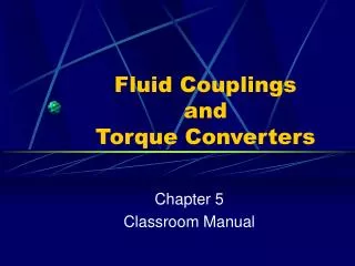
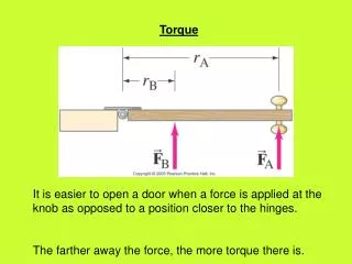
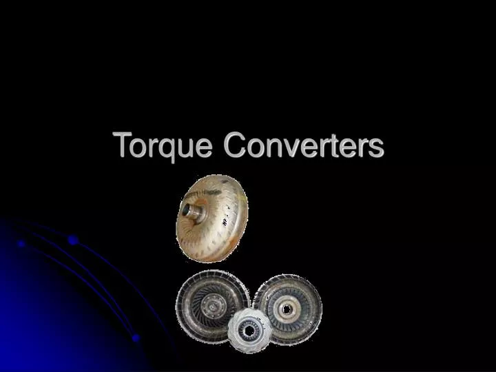
Torque Converters. Purpose. Allow the vehicle to come to a complete stop without stalling the engine Provide torque multiplication to allow smooth acceleration from a stop House a torque converter clutch which will eliminate torque converter slippage at highway speeds.

E N D
Purpose • Allow the vehicle to come to a complete stop without stalling the engine • Provide torque multiplication to allow smooth acceleration from a stop • House a torque converter clutch which will eliminate torque converter slippage at highway speeds
Parts of a Torque Converter • Housing • Hub • Impeller • Split ring guide • Turbine • Split ring guide • Stator • Stator one-way clutch • Torque converter clutch • Apply piston
Principles of Operation • A torque converter is a type of fluid coupling • There is no direct mechanical link between the input (engine flywheel) and the output (transmission input shaft) • The impeller (pump of the torque converter) forces fluid through the turbine, which forces the turbine to turn • The turbine is splined to the transmission input shaft
Principles of Operation Impeller Turbine
Fluid Coupling Problems • When there is a large difference in RPM between the impeller and the turbine in a fluid coupling, the fluid coming off the turbine strikes the impeller opposite the direction of rotation, thus slowing the impeller down (robbing power)
Fluid Coupling Solutions • By incorporating a stator into a fluid coupling we can overcome the problem of turbine discharge oil slowing down the impeller Stator
Split Ring Guide • Guides the fluid flow during vortex flow conditions
Phases of Operation • Torque multiplication • Relatively low impeller (engine) RPM’s • Stator is locked into place by its one-way clutch • Vortex fluid flow within the converter • Coupling phase • Occurs at approx. 35-40 MPH under “normal” driving conditions • No torque multiplication • Stator is freewheeling • Turbine is spinning at approx 90% of impeller speed • Rotary flow within the converter
Torque Multiplication • Because the turbine discharge oil is redirected so that it hits the impeller in the direction of impeller rotation, it helps the engine “turn” the impeller. • This is what causes torque multiplication
Torque Multiplication • Torque converters can multiply torque at a 2:1 to 3:1 ratio • Exact amount depends on the design of the impeller, stator, and turbine and impeller RPM • The point at which maximum torque multiplication occurs is near the stall speed of the converter • During the torque multiplication phase, turbine speed is significantly lower than impeller speed • A torque converter attached to an engine producing 200 ft/lbs of torque would deliver 500 ft/lbs of torque to the input shaft of the transmission (with a 2.5:1 torque multiplication ratio) • Fluid flow is vortex
Vortex Flow • During vortex flow the fluid is circulating from the impeller to the stator to the turbine and then back to the impeller Cross-Section of Torque Converter
Coupling Phase • As turbine (vehicle) speed increases and approaches the speed of the impeller the turbine discharge oil is accelerated to the point that it no longer strikes the front side of the stator blades, instead it strikes the backside of the stator blade causing the stator one-way clutch to unlock and the stator to freewheel • Since the stator is unlocked, fluid is not redirected and no torque multiplication occurs • Fluid flow is rotary
Rotary Flow • As the speed of the turbine approaches the speed of the impeller fluid flow switches from vortex to rotary • After the fluid is discharged from the turbine it is not redirected by the stator, instead it rotates with torque converter Front-View of Torque Converter
Stall Speed • Stall speed is the engine RPM at which the torque converter has coupled enough that with the wheels locked the engine is not able to increase RPM any further
Stall Speed • Types of stall Speeds • True stall • This is the maximum rpm the engine can attain with the driveline completely locked • Generally can only be attained with a trans-brake • Brake stall • This is the maximum rpm the engine can attain with the brakes applied • The brakes generally will not have enough holding power to allow the engine to reach true stall speed • Flash stall • This is the rpm at which, when you accelerate at full throttle from a dead stop the engine RPM “flashes” to • TCI’s recommended method of testing stall speed
Stall Tests • CAUTION • Do not brake stall a converter for more than 10 seconds at a time. • During a brake stall 100% of the power developed by the engine is converted in heat in the torque converter. • Wait at least 2 minutes between brake stall tests
Factors Affecting Stall Speed • Vehicle Weight • Vane/Fin Angle • Horsepower • Impeller to Turbine Clearance • Powerband/Camshaft • Stator Design • Torque Rate • Converter Diameter • Gear Ratio
Vane Design Depending on the design and pitch of the blades, the impeller will “scoop” the most oil at a specific RPM, thus altering the stall speed
Stator Design • By altering the stator design, stall speed and torque multiplication ratios can be altered Stock Aftermarket
Selecting the Proper Stall Speed Converter • For non-stock engine-vehicle combinations the stock torque converter may not be optimal • Work with a torque converter company to choose the correct torque converter • Remember – Torque converter design involves trade-offs