Download
1 / 25
250 likes | 317 Views
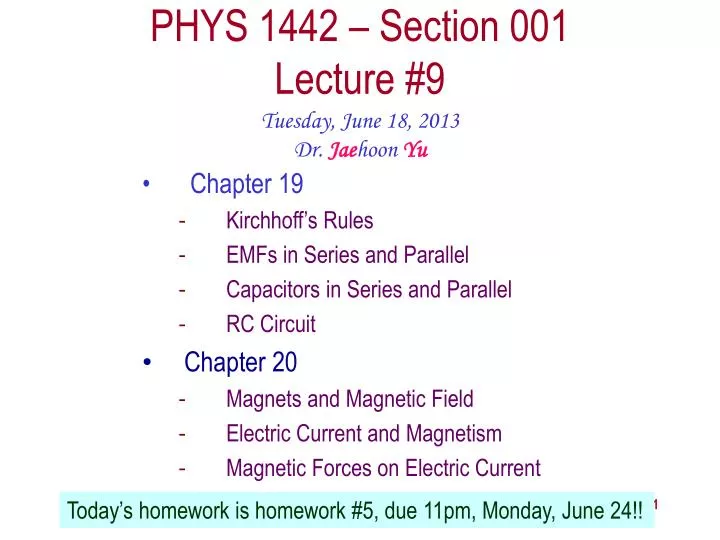
PHYS 1442 – Section 001 Lecture #9. Tuesday , June 18, 2013 Dr. Jae hoon Yu. Chapter 19 Kirchhoff’s Rules EMFs in Series and Parallel Capacitors in Series and Parallel RC Circuit Chapter 20 Magnets and Magnetic Field Electric Current and Magnetism

E N D
PHYS 1442 – Section 001Lecture #9 Tuesday, June 18, 2013 Dr. Jaehoon Yu • Chapter 19 • Kirchhoff’s Rules • EMFs in Series and Parallel • Capacitors in Series and Parallel • RC Circuit • Chapter 20 • Magnets and Magnetic Field • Electric Current and Magnetism • Magnetic Forces on Electric Current Today’s homework is homework #5, due 11pm, Monday, June 24!! PHYS 1442-001, Summer 2013 Dr. Jaehoon Yu
Announcements • Quiz results • Class average: 58.1/95 • Equivalent to 61.2/100 • Previous result 51.7/100 • Top score: 87/95 • Mid-term exam • Tomorrow, Wednesday, June 19 • Comprehensive exam • Covers CH16.1 – what we finish today (CH20.1?) plus Appendices A1 – A8 • Mid-term grade discussion • Between 2 – 3:30 pm this Friday, June 21 • In Dr. Yu’s office (CPB342) PHYS 1442-001, Summer 2013 Dr. Jaehoon Yu
Special Project #3 • Make a list of the power consumption and the resistance of all electric and electronic devices at your home and compiled them in a table. (5 points total for the first 10 items and 0.25 points each additional item.) • Estimate the cost of electricity for each of the items on the table using your own electric cost per kWh (if you don’t find your own, use $0.12/kWh) and put them in the relevant column. (2 points total for the first 10 items and 0.1 points each additional items) • Estimate the the total amount of energy in Joules and the total electricity cost per day, per month and per year for your home. (6 points) • Due: Beginning of the class Thursday, June 20 • Print the entire width of the table to be contained in one page!! PHYS 1442-001, Summer 2013 Dr. Jaehoon Yu
Spread Sheet PHYS 1442-001, Summer 2013 Dr. Jaehoon Yu
Kirchhoff’s Rules – 1st Rule • Some circuits are very complicated to analyze using the simple combinations of resisters • G. R. Kirchhoff devised two rules to deal with complicated circuits. • Kirchhoff’s rules are based on conservation of charge and energy • Kirchhoff’s 1st rule: Junction rule, charge conservation. • At any junction point, the sum of all currents entering the junction must equal to the sum of all currents leaving the junction. • In other words, what goes in must come out. • At junction a in the figure, I3 comes into the junction while I1 and I2 leaves: I3 = I1+ I2 PHYS 1442-001, Summer 2013 Dr. Jaehoon Yu
Kirchhoff’s Rules – 2nd Rule • Kirchoff’s2nd rule: Loop rule, uses conservation of energy. • The sum of the changes in potential around any closed path of a circuit must be zero. • The current in the circuit in the figure is I=12/690=0.017A. • Point e is the highest potential point while point d is the lowest potential. • When the test charge starts at e and returns to e, the total potential change is 0. • Between point e and a, no potential change since there is no source of potential or any resistance to drop potential. • Between a and b, there is a 400Ω resistance, causing IR=0.017*400 =6.8V drop. • Between b and c, there is a 290Ω resistance, causing IR=0.017*290 =5.2V drop. • Since these are voltage drops, we use negative sign for these, -6.8V and -5.2V. • No change between c and d while from d to e there is +12V change. • Thus the total change of the voltage through the loop is: -6.8V-5.2V+12V=0V. PHYS 1442-001, Summer 2013 Dr. Jaehoon Yu
Using Kirchhoff’s Rules • Determine the flow of currents at the junctions. • It does not matter which direction of the current you choose. • If the value of the current after completing the calculations are negative, you just flip the direction of the current flow. • Write down the current equation based on Kirchhoff’s 1st rule at various junctions. • Be sure to see if any of them are the same. • Choose independent closed loops in the circuit • Write down the potential in each interval of the junctions, keeping the signs properly. • Write down the potential equations for each loop. • Solve the equations for unknowns. PHYS 1442-001, Summer 2013 Dr. Jaehoon Yu
Using Kirchhoff’s rules. Calculate the currents I1, I2 and I3 in each of the branches of the circuit in the figure. Example 19 – 8 The directions of the current through the circuit is not known a priori but since the current tends to move away from the positive terminal of a battery, we arbitrarily choose the direction of the currents as shown. We have three unknowns so we need three equations. Using Kirchhoff’s junction rule at point a, we obtain This is the same for junction d as well, so no additional information. Now the second rule on the loop ahdcba. The total voltage change in loop ahdcba is. PHYS 1442-001, Summer 2013 Dr. Jaehoon Yu
Example 19 – 8, cnt’d Now the second rule on the other loop agfedcba. The total voltage change in loop agfedcba is. So the three equations become We can obtain the three current by solving these equations for I1, I2 and I3. PHYS 1442-001, Summer 2013 Dr. Jaehoon Yu
EMF’s in Series and Parallel: Charging a Battery • When two or more sources of emf’s, such as batteries, are connected in series • The total voltage is the algebraic sum of their voltages, if their direction is the same • Vac=1.5 + 1.5=3.0V in figure (a). • If the batteries are arranged in an opposite direction, the total voltage is the difference between them Parallel arrangements (c) are used only to increase currents. • Vac=20 – 12=8.0V in figure (b) • Connecting batteries in opposite direction is wasteful. • This, however, is the way a battery charger works. • Since the 20V battery is at a higher voltage, it forces charges into 12V battery • Some battery are rechargeable since their chemical reactions are reversible but most the batteries can not reverse their chemical reactions This is the way we jump start a car PHYS 1442-001, Summer 2013 Dr. Jaehoon Yu
Capacitors in Series or Parallel • Capacitors are also used in many electric circuits. • So what is an electric circuit again? • A closed path of conductors, usually wires, connecting capacitors, resisters and other electrical devices, in which • charges can flow • And includes a source of potential such as a battery • Capacitors can be connected in various ways. • In parallel and in Series or in combination PHYS 1442-001, Summer 2013 Dr. Jaehoon Yu
Capacitors in Parallel • Parallel arrangement provides the same voltage across all the capacitors. • Left hand plates are at Va and right hand plates are at Vb • So each capacitor plate acquires charges given by the formula • Q1=C1V, Q2=C2V, and Q3=C3V • The total charge Q that must leave the battery is then • Q=Q1+Q2+Q3=V(C1+C2+C3) • Consider that the three capacitors behave like an equivalent one • Q=CeqV= V(C1+C2+C3) • Thus the equivalent capacitance in parallel is PHYS 1442-001, Summer 2013 Dr. Jaehoon Yu What is the net effect? The capacitance increases!!!
Series arrangement is more interesting • When a battery is connected, +Q flows to the left plate of C1 and –Q flows to the right plate of C3 inducing opposite sign charges on the other plates. • Since the capacitor in the middle was originally neutral, charges get induced to neutralize the induced charges Capacitors in Series • So the charge on each capacitor is the same value, Q. (Same charge) • Consider that the three capacitors behave like an equivalent one • Q=CeqV V=Q/Ceq • The total voltage V across the three capacitors in series must be equal to the sum of the voltages across each capacitor. • V=V1+V2+V3=(Q/C1+Q/C2+Q/C3) • Putting all these together, we obtain: • V=Q/Ceq=Q(1/C1+1/C2+1/C3) • Thus the equivalent capacitance is PHYS 1442-001, Summer 2013 Dr. Jaehoon Yu What is the net effect? The capacitance smaller than the smallest C!!!
Example 19 – 10 Equivalent Capacitor: Determine the capacitance of a single capacitor that will have the same effect as the combination shown in the figure. Assume C1=C2=C3=C. We should do these first!! How? These are in parallel so the equivalent capacitance is: Now the equivalent capacitor is in series with C1. Solve for Ceq PHYS 1442-001, Summer 2013 Dr. Jaehoon Yu
Resister and Capacitor Arrangements • Parallel Capacitor arrangements • Parallel Resister arrangements • Series Capacitor arrangements • Series Resister arrangements PHYS 1442-001, Summer 2013 Dr. Jaehoon Yu
RC Circuits • Circuits containing both resisters and capacitors • RC circuits are used commonly in everyday life • Control windshield wiper • Timing of traffic light color change • Camera flashes and heart pacemakers • How does an RC circuit look? • There should be a source of emf, capacitors and resisters • What happens when the switch S is closed? • Current immediately starts flowing through the circuit. • Electrons flows out of negative terminal of the emf source, through the resister R and accumulates on the upper plate of the capacitor • The electrons from the bottom plate of the capacitor flow into the positive terminal of the battery, leaving only positive charge on the bottom plate • As the charge accumulates on the capacitor, the potential difference across it increases • The current reduces gradually to 0 until the voltage across the capacitor is the same as emf. • The charge on the capacitor increases unilit reaches to its maximum, Cε. • What happens when the battery in the circuit is replaced with a wire? Capacitor discharges PHYS 1442-001, Summer 2013 Dr. Jaehoon Yu
RC Circuits • How does all this look like in graphs? • Charge and the current on the capacitor as a function of time • From energy conservation (Kirchhoff’s 2nd rule), the emfεmust be equal to the voltage drop across the capacitor and the resister • ε=IR+Q/C • R includes all resistance in the circuit, including the internal resistance of the battery, I is the current in the circuit at any instant, and Q is the charge of the capacitor at that same instance. PHYS 1442-001, Summer 2013 Dr. Jaehoon Yu
Analysis of RC Circuits • Charge and voltage • What can we see from the above equations? • Q and VC increase from 0 at t=0 to maximum value Qmax=Cε and VC= ε. • In how much time? • The quantity RC is called the time constant, τ, of the circuit • τ=RC, What is the unit? • What is the physical meaning? • The time required for the capacitor to reach (1-e-1)=0.63 or 63% of its full charge • The current is Sec. PHYS 1442-001, Summer 2013 Dr. Jaehoon Yu
Discharging RC Circuits • When a capacitor is already charged, it is allowed to discharge through a resistance R. • When the switch S is closed, the voltage across the resistor at any instant equals that across the capacitor. Thus IR=Q/C. • The rate at which the charge leaves the capacitor equals the negative of the current flows through the resistor • I= - ΔQ/Δt. Why negative? • Since the current is leaving the capacitor • Thus the voltage equation becomes a differential equation Rearrange terms PHYS 1442-001, Summer 2013 Dr. Jaehoon Yu
Discharging RC Circuits • What happens when an RC circuit discharges from its original charge of Q0? • Charge at any given time t is • What does this tell you about the charge on the capacitor? • It decreases exponentially with time at a time constant RC • Just like the case of charging • The current is: • The voltage is: PHYS 1442-001, Summer 2013 Dr. Jaehoon Yu
Discharging RC circuit. If a charged capacitor C=35μF is connected to a resistance R=120Ω as in the figure, how much time will elapse until the voltage falls to 10% of its original (maximum) value? Ex. 19 – 12 What is the RC time of this circuit? The RC time Since we are looking for the time it takes for Vc=10% of V0, we obtain For 0.1V0 Rearrange terms Solve for t PHYS 1442-001, Summer 2013 Dr. Jaehoon Yu
Application of RC Circuits • What do you think the charging and discharging characteristics of RC circuits can be used for? • To produce voltage pulses at a regular frequency • How? • The capacitor charges up to a particular voltage and discharges • A simple way of doing this is to use breakdown of voltage in a gas filled tube • The discharge occurs when the voltage breaks down at V0 • After the completion of discharge, the tube no longer conducts • Then the voltage is at V0’ and it starts charging up • How do you think the voltage as a function of time look? • A sawtooth shape • Pace maker, intermittent windshield wiper, etc PHYS 1442-001, Summer 2013 Dr. Jaehoon Yu
Magnetism • What are magnets? • Objects with two poles, north and south poles • The pole that points to geographical north is the north pole and the other is the south pole • Principle of compass • These are called magnets due to the name of the region, Magnesia, where rocks that attract each other were found • What happens when two magnets are brought to each other? • They exert force onto each other • What kind? • Both repulsive and attractive forces depending on the configurations • Like poles repel each other while the unlike poles attract PHYS 1442-001, Summer 2013 Dr. Jaehoon Yu
Magnetism • So the magnet poles are the same as the electric charge? • No. Why not? • While the electric charges (positive and negative) can be isolated the magnet poles cannot be isolated. • So what happens when a magnet is cut? • If a magnet is cut, two magnets are made. • The more they get cut, the more magnets are made • Single pole magnets are called the monopole but it has not been seen yet • Ferromagnetic materials: Materials that show strong magnetic effects • Iron, cobalt, nickel, gadolinium and certain alloys • Other materials show very weak magnetic effects PHYS 1442-001, Summer 2013 Dr. Jaehoon Yu
Magnetic Field • Just like the electric field that surrounds electric charge, a magnetic field surrounds a magnet • What does this mean? • Magnetic force is also a field force • The force one magnet exerts onto another can be viewed as the interaction between the magnet and the magnetic field produced by the other magnet • What kind of quantity is the magnetic field? Vector or Scalar? • So one can draw magnetic field lines, too. Vector • The direction of the magnetic field is tangent to a line at any point • The direction of the field is the direction the north pole of a compass would point to • The number of lines per unit area is proportional to the strength of the magnetic field • Magnetic field lines continue inside the magnet • Since magnets always have both the poles, magnetic field lines form closed loops unlike electric field lines PHYS 1442-001, Summer 2013 Dr. Jaehoon Yu