Download
1 / 34
340 likes | 532 Views
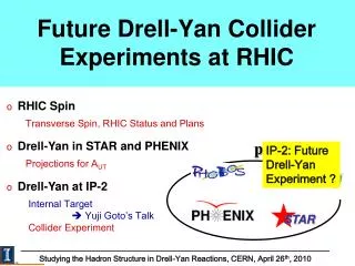
The RHIC Collider. Collider Workshop, JLAB, February 24, 2009. Fulvia Pilat. RHIC Collider Complex. 100x100 GeV/ u ions 250x250 GeV polarized p Chronology: 1996 commissioning AtR 1998 sextant test 1999 engineering runs 2000 first collisions 10 years of operations. Outline.

E N D
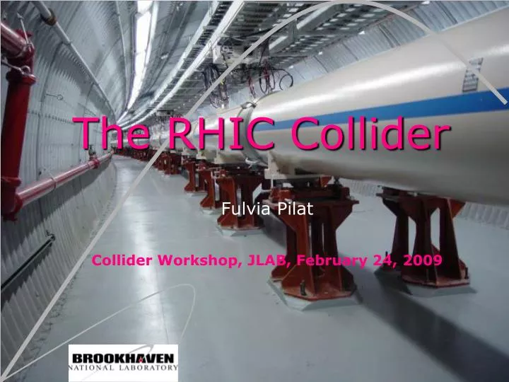
The RHIC Collider Collider Workshop, JLAB, February 24, 2009 Fulvia Pilat
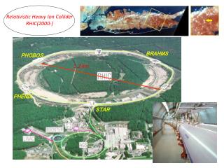
RHIC Collider Complex 100x100 GeV/u ions 250x250 GeV polarized p Chronology: 1996 commissioning AtR 1998 sextant test 1999 engineering runs 2000 first collisions 10 years of operations
Outline • Introduction • Collider design and evolution Optics, interaction regions, correction systems Validation of design and correction schemes Operational use of corrections systems (ex: IR corrections) • Commissioning operations: increasing machine performance example: lower beta* • Recent developments Stochastic cooling of bunched beams Tune, coupling, orbit and chromaticity feedback • Lesson learned from RHIC
Corrections systems • Orbit correction BPM + dipole correctors • Coupling correction 3 families of skew quads 120 deg in the arcs (2 wired up in software orthogonal system) 1 skew quad/triplet for local compensation of the roll misalignment of the triplet quads (no experimental solenoid compensators – all done by the skew quad families) • Chromatic corrections 2 families of sextupoles in the arcs linear chromaticity 4 additional sextupole families in arcs nonlinear chromaticity (added later) • IR correction packages (each triplet) 1 dipole H, 1 dipole V, 1 skew quadrupole 1 normal and 1 skew sextupole 2 octupoles 1 decapole 2 dodecapoles (skew octupole and dodecapole layers exists but are not powered)
Validation of design and correction schemes In the design phase we did extensive modeling and simulations to validate the design and the correction schemes Built a offline machine model for extensive DA simulations, including: • Optics configurations • Measured magnetic errors in arc and IR magnets • Measured misalignments and roll errors in cold masses and cryostats • Beam-beam (weak-strong approximation) Other performance issues dealt with stand-alone codes: • Intra-beam scattering • Beam-beam (strong-strong) • Electron cloud • Polarization tracking Selected capabilities of the offline model are part of the online machine model But, over the operational life of the machine we ended relying mostly on beam based corrections (orbit, coupling, IR corrections, nonlinear chromaticity)
IR correction method - theory • The magnetic errors in an accelerator magnet can be described in terms of the multipole errors anand bndefined as: • An excursion of the local orbit through a region having non-linear fields generates feed-down effects to lower order field harmonics • The most useful observable effects come from the feed-down to the beam closed orbit and betatrontunes • It is possible in theory to infer local non-linear effects both from the measure of residual RMS orbit and of tune shifts generated by a local orbit bump in the IR. Given existing limitations on the resolution of the orbit measurement and on the allowable bump amplitude at the triplets, in practice we have used so far almost exclusively the measurement of tune shift as a function of bump amplitude for non-linear correction • The measured tune shifts arise from either the feed-down to the normal gradient or from the repelling effect of linear coupling • The tune shift (ΔQ) and the linear coupling term (Δc) for different bump planes (H and V) and for different multipole errors (normal, skew, even and odd orders) can be expressed as follows (where cn is either the anor bnand zis xor y): : • This table implies that for reasonable measurement of a tune shift due to I.R. magnetic field errors, the following bump types should be used to identify the relevant multipole: horizontal for Sextupole(b2), vertical for Skew Sextupole (a2), horizontal and vertical for octupole (b3) etc. A diagonal bump for skew octupole is necessary In order to simplify the identification of individual multipoles using the observed tune shifts, the conditions should be such that the tuneshifts produced by coupling are negligible when compared with the tune shifts from the normal gradient change Where the functions g and h are defined as:
Example: normal sextupole IR correction Schematics of IR bumps Tune shift vs. amplitude Before correction Tune shift vs. amplitude After sextupole correction Before Correction After Correction
Example: skew quadrupole IR correction Beam decay evolution during the correction Bump power supply Tune shift vs. amplitude Before correction Tune shift vs. amplitude After skew sextupole correction After Correction Before Correction
Example: octupole IR correction Horizontal Tune Shift Before Correction Before correction H Vertical Tune Shift Before Correction Before correction V After correction Tune Shifts After Correction
“The tune modulation (10 Hz due to triplet vibration via feed-down effect; that is, tune modulation due to off-axis beam in sextupoles driven by off-axis beam in triplet quads) was observed to reduce by a factor of 2-3 after non-linear corrections. Correction benefits: reduction of tune modulation
15 Operational correction for IR decapole and dodecapole Generic scanner • scans magnet strength (for list of magnets) • observes beam loss rate • minimizes beam loss rate with strength
16 Decapole/Dodecapole correction result 10998 Tested effect of 10- and 12-pole correctors on beam loss rate by switching off all correctors
17 Estimate of luminosity gain
Nonlinear chromaticity– Run 10 experience • Momentum aperture essential for re-bucketing at store (turn on 196 MHz RF system at store – on top of the accelerating 28 MHz RF system to get more beam in the experiment acceptance) • Nonlinear chromaticity reduces the available momentum aperture • 2nd order chromaticity minimized for phase advance of (2n+1)*p/2 between 2 equal IP’s • Running now with increased arc phase advance from 86 to 93deg/cell (IBS reduction lattice, lower dispersion in the arcs) • Also lower beta* (0.6m instead of 1m) reduced aperture in the triplets • Insufficient momentum aperture for re-bucketing Tried nonlinear chromaticity corrections but measurements not reliable at small radial offsets Had to step back beta* from 0.6m to 0.7m and shift the tunes for momentum aperture
Outline • Introduction • Collider design and evolution Optics, interaction regions, correction systems Validation of design and correction schemes Operational use of corrections systems (ex: IR corrections) • Commissioning operations: increasing machine performance example: lower beta* • Recent developments Stochastic cooling of bunched beams Tune, coupling, orbit and chromaticity feedback • Lesson learned from RHIC
Performance increase Heavy ion runs Polarized proton runs Integrated luminosity L [pb-1] Integrated nucleon-pair luminosity LNN [pb-1] Increase: Bunch intensity (limits: instabilities) Number of bunches (limits: electron cloud) Total intensity (limits: losses, beam-beam) Decrease: Beta star (limits: aperture, lifetime) Emittance (via stochastic cooling and electron cooling at low energies)
Beta* squeeze at RHIC GOALS: • Increase of luminosity • Preparation for dynamic beta* squeeze with transverse stochastic cooling HISTORY:
Beta* squeeze: methodology • Before beam • the optics matching to lower b* in IP6 and IP8 is turned into a ramp with ramp application software The ramp, typically 300 s, is first tested withoutbeam for power supplylimits and the quench protection system. • Ramp development • Ramp development follows with 6-12 bunches/ ring. Care is taken to avoid transverse emittance growth to avoid losses in the aperture limiting triplets. The ramps are done with tune & coupling feedback. Orbits are corrected to to 0.1-0.2 mm rms • Store set-up • We tune for lifetime at store (orbit, tunes, coupling, and chromaticity), then steer for collisions, compare rates and test collimation. Optics measurements with the AC dipole follow.Measuredb*are typically in within 10-15% from nominal, and b*is also verified with Vernier scans in operation. • Test of physics ramp and store • We test the new configuration with a physics store (56-109 bunches/ring for ramp transmission, collimation, experimental backgrounds. If successful we can use the lower b* in operations. We then readjust non-linear corrections for the new configuration, namely local IR triplet correction and possibly non-linear chromaticity corrections.
Example results: d-Au Run-8 • We first reduced b* in the yellow ring (gold), where we ran a lattice with higher phase advance per arc cell to minimize intra beam scattering effects. After 2 attempts, the 3rd ramp with tune & coupling feedback brought the beam to store with good transmission • A 56x56 physics ramp allowed us to establish that the normalized collision rates ratios between the baseline (yellow at 1m) and the one with squeezed optics (yellow at 0.70m) yielded the expected 15% luminosity increase. • Once we established the feasibility of operations with yellow at b*=0.7m, we repeated the development for the blue ring, running deuterons. The entire development took an integrated beam time of ~24h, over a few days. We ran the reminder of the d-Au run with b*=0.7m in both rings, gaining~30% in integrated luminosity increase for the run.
Outline • Introduction • Collider design and evolution Optics, interaction regions, correction systems Validation of design and correction schemes Operational use of corrections systems (ex: IR corrections) • Commissioning operations: increasing machine performance example: lower beta* • Recent developments Stochastic cooling of bunched beams Tune, coupling, orbit and chromaticity feedback • Lesson learned from RHIC
Dynamic beta* squeeze– Motivation • Run10: longitudinal and vertical Stochastic Cooling (SC) are operational => potential for luminosity increase improve luminosity by a ~factor 2 • The goal is to have an application similar to the one used for orbit correction at store: β* as a function of time should follow the change in emittance as achieved by Stochastic Cooling. • To help reaching higher peak luminosity, an application is being developed using the RHIC online model to further push the squeeze of β* in the experimental insertions IR6 and IR8.
Stochastic cooling system 2006: first test of longitudinal cooling 2007: longitudinal cooling operational 2009: first transversetestsysteminstalled and tested “signal suppression” demonstrated: feedback off feedback on 2010: first test of transverse cooling of ion beams 2012: 200 GeV, Au+Au, full stochastic cooling RHIC luminosity upgrade (for ions): Au+Au, 200 GeV: 40 × 1026 cm-2s-1 (×4) (with * = 0.5 m, 56 MHz rf cavity) M. Blaskiewicz, J.M. Brennan
SystemSchematics • New pickup, Blue longitudinal • New pickup, Yellow longitudinal • Microwave link, upgraded kicker (9 GHz), new low-level enclosure • New pickup, Blue vertical (from 1.) • New kicker, Blue vertical
Predictions for longitudinal cooling Run-10 Current profile at 0, 2.5 and 5 hours without burn-off. 4 MV on storage system, IBS suppression lattice (Vertical cooling only dQmin=0.01, dQbare=0)
Blue longitudinal cooling – measurements Run-10 System status: Yellow transverse operational Yellow longitudinal being repaired Blue transverse operational Blue longitudinal operational (surprise: ring cross talk)
Orbit, Tune & Coupling, Chromaticity, 10Hz feedbacks dynamic reference orbit control and feed-forward demonstrated (02/04/10) orbit successful ramp to store (02/04/10) tune extensively improved in Run-9 fully operational in Run-10 coupling ready for test chromaticity To counteract 10 Hz orbit jitter from triplet vibrations Under development “10 Hz” RHIC Weekly Meeting, February 8, 2010
Ramp development with continuous orbit and tune/coupling feedback orbit rms in the yellow ring orbit rms in the blue ring orbit feedback OFF orbit feedback ON Nb 6 Nppb ~ 1E9 (Au) SVD tolerance 100 FB gain 10% / 10% APEX Meeting, February 5, 2010
Chromaticity measurements (prep for feedback) Chromaticity measurement algorithm improved: extracts chromaticity from ‘wiggled’ tunes blue ring, ramp chromaticity measurement yellow ring, ramp chromaticity measurement xy xy xx xx Qx Qx Qy Qy 01/08/10 01/08/10 ready for chromaticity feedback test RHIC Weekly Meeting, February 8, 2010
conclusions Disclaimer: RHIC in operations for 10 years – thousands of design and operational issues not covered in this talk Lessons learned: • Flexibility in the design pays off in operations and performance (example beta*) • Beam-based corrections play a critical role in a SC hadron collider • Stochastic cooling of bunched beams is a reality – although a very specialized one. Could/Should become part of the design of new hadron colliders at high energies. • Feedback systems enhance performance and operability of a hadron collider (Available to discuss topics not covered here)
APEX STAR Polarity