Download
1 / 103
1.26k likes | 1.92k Views
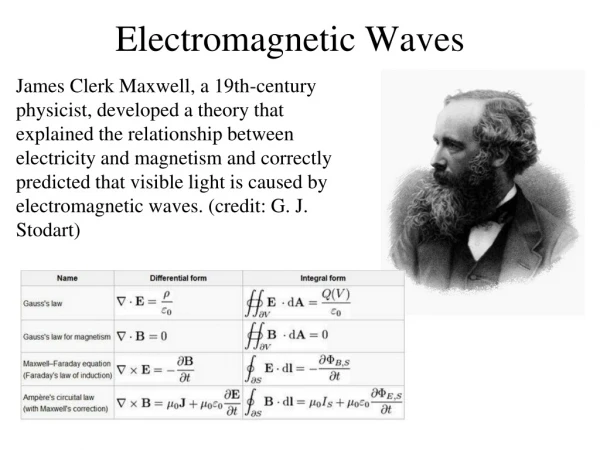
Electromagnetic Waves and Optics. Physics Unit 11 Chapters 24-27. 24.1 Maxwell’s Equations 24.2 Production of EM Waves. James Clerk Maxwell – Scottish physicist who showed that electricity and magnetism together create electromagnetic waves Maxwell’s Equations Gauss’s Law

E N D
Electromagnetic Waves and Optics Physics Unit 11 Chapters 24-27
24.1 Maxwell’s Equations24.2 Production of EM Waves • James Clerk Maxwell – Scottish physicist who showed that electricity and magnetism together create electromagnetic waves • Maxwell’s Equations • Gauss’s Law • Gauss’s Law for Magnetism (no magnetic monopoles) • Faraday’s Law • Ampere’s Circuit Law
24.1 Maxwell’s Equations24.2 Production of EM Waves • Maxwell predicted that the speed of electromagnetic waves would be • Heinrich Hertz was the first scientist to generate and receive EM waves.
24.1 Maxwell’s Equations24.2 Production of EM Waves • Creation of electromagnetic waves • Two wires are connected to either side of an AC generator to form an antenna. • As the emf of the generator changes a potential difference between the ends of the wires is created. • The potential difference makes an electric field. • As the AC generator changes polarity, the electric field direction is reversed.
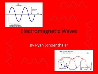
24.1 Maxwell’s Equations24.2 Production of EM Waves • Also, as the potential difference changes directions, the charges in the antenna run to the other ends creating a current. • Current creates a B-field perpendicular to the wire. • Electromagnetic waves are both E-field and B-field. • Field are perpendicular to each other and the direction of travel. • Transverse waves.
24.1 Maxwell’s Equations24.2 Production of EM Waves • To detect EM waves • Need antenna to receive either E-field or B-field. • E-field – Straight antenna • The E-field causes electrons to flow in the opposite direction creating current that changes with time as the E-field changes. • The circuitry attached to the antenna let you pick the frequency (LC-circuit) and amplify it for speakers.
24.1 Maxwell’s Equations24.2 Production of EM Waves • B-field – Loop antenna • The B-field flowing through the loop induces a current that changes as the B-field changes.
24.1 Maxwell’s Equations24.2 Production of EM Waves • Relating the E-field and B-field strengths • Stronger E-field creates greater current which makes greater B-field
24.1 Maxwell’s Equations24.2 Production of EM Waves • EM waves can travel through a vacuum or material because E- and B-fields can exist in both. • All EM waves travel the same speed in a vacuum. • Frequency of the wave is determined by the source.
Day 110 Homework • Produce waves. Do homework. • 24P1, 3-4 • Read 24.3, 24.4 • 24CQ12, 16, 20 • Answers: • 1) m/s • 3) 150 kV/m • 4) 1 kV/m
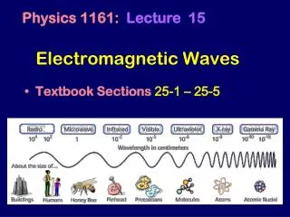
24.3 The EM Spectrum24.4 Energy in EM Waves • For all waves v = fλ • For EM waves in vacuum v = c = 299792458 m/s • This is exact and is used to define the meter • As EM waves travel through other substances, like plastic, it travels slower. • So c = fλ
24.3 The EM Spectrum24.4 Energy in EM Waves • An EM wave has a frequency of 90.7 MHz. What is the wavelength of this wave? What type of EM wave is it? • λ = 3.31 m • Radio wave (FM)
24.3 The EM Spectrum24.4 Energy in EM Waves • Wave’s energy is proportional to the amplitude squared • Wave’s intensity and
24.3 The EM Spectrum24.4 Energy in EM Waves • A certain microwave oven can produce 1500 W of microwave radiation over an area that is 30 cm by 30 cm. • What is the intensity in W/m2? • Calculate the peak electric field strength, , in these waves. • What is the peak magnetic field strength, ?
Day 111 Homework • These are a whole spectrum of problems. • 24P6, 8, 10, 14-17, 25-26, 30, 32-33, 35 • Read 25.1, 25.2, 25.3 • 25CQ1-2, 5-6 • Answers • 6) 11.7 cm • 8) 26.96 MHz • 10) Hz • 14) 0.600 m • 15) s, s • 16) Hz, X-rays • 17) 500 s • 25) m • 26) m, % • 30) 20.7 W/m2 • 32) 318 W/m2, T, 490 V/m • 33) W/m2 • 35) W/m2, W, 1.12 W
25.1 The Ray Aspect of Light25.2 The Law of Reflection25.3 The Law of Refraction • Law of Reflection: θr = θi • Specular Reflection • Parallel light rays are reflected parallelly • Diffuse Reflection • Parallel light rays are scattered by irregularities in the surface.
25.1 The Ray Aspect of Light25.2 The Law of Reflection25.3 The Law of Refraction Plane Mirror • Image is upright • Image is same size • Image is located as far behind the mirror as you are in front of it
25.1 The Ray Aspect of Light25.2 The Law of Reflection25.3 The Law of Refraction • Since light rays appear to come from behind mirror, the image is called a virtual image. • If light rays appear to come from a real location, the image is called a real image. • Real images can be projected on a screen, virtual images cannot. • Plane mirrors only produce virtual images.
25.1 The Ray Aspect of Light25.2 The Law of Reflection25.3 The Law of Refraction • How long must a plane mirror be to see your whole reflection? • From half way between your eyes and floor to half way between your eyes and the top of your head.
25.1 The Ray Aspect of Light25.2 The Law of Reflection25.3 The Law of Refraction • Speed of light in a vacuum: • m/s • Light travels slower through materials due to light hitting, absorbed by, emitted by, and scattered by atoms. • Index of Refraction • Number to indicate relative speed of light in a material
25.1 The Ray Aspect of Light25.2 The Law of Reflection25.3 The Law of Refraction • When light hits the surface of a material part of it is reflected • The other part goes into the material • The transmitted part is bent (refracted)
25.1 The Ray Aspect of Light25.2 The Law of Reflection25.3 The Law of Refraction • Snell’s Law (The Law of Refraction) • Where • n1 = index of refraction of incident medium • n2 = index of refraction of second medium • θ1 = angle of incidence (measured to normal) • θ2 = angle of refraction (measured to normal)
25.1 The Ray Aspect of Light25.2 The Law of Reflection25.3 The Law of Refraction • You shine a laser into a piece of clear material. The angle of incidence is 35°. You measure the angle of refraction as 26°. What is the material? • Ice • What is the speed of light in the material? • m/s
Day 112 Homework • Let your answers reflect the truth. • 25P1-3, 5, 7-8, 11-13 • Read 25.4, 25.5 • 25CQ11, 13 • Answers • 1) bottom 0.825 m, top 1.715 m; not related • 2) • 3) • 5) m/s, m/s • 7) 1.490, polystyrene • 8) ice at 0° C • 11) 1.03 ns • 12) 2.93 m, 1.37 m • 13) 1.46, fused quartz
25.4 Total Internal Reflection25.5 Dispersion: Rainbows and Prisms • Total Internal Reflection • When light hits a interface between two types of media with different indices of refractions • Some is reflected • Some is refracted • Critical angle • Angle of incidence where refracted angle is 90 • Angles of incidence larger than this cause the refracted angle to be inside the material. This can’t happen, so no refraction occurs.
25.4 Total Internal Reflection25.5 Dispersion: Rainbows and Prisms • Critical angle • Where
25.4 Total Internal Reflection25.5 Dispersion: Rainbows and Prisms • What is the critical angle from cubic zirconia (n=2.16) to air? Will an angle of produce total internal reflection? • 27.7 • No
25.4 Total Internal Reflection25.5 Dispersion: Rainbows and Prisms • Uses of total internal reflection • Fiber optics for • Endoscopes • Telecommunications • Decorations • Binoculars/telescopes • Makes them shorter • Reflectors • Gemstones • Cut so that light only exits at certain places
25.4 Total Internal Reflection25.5 Dispersion: Rainbows and Prisms • Dispersion • Each wavelength of light has a different index of refraction • Red — lowest • Violet — highest • When light is refracted, the violet bends more than red, which splits the colors
25.4 Total Internal Reflection25.5 Dispersion: Rainbows and Prisms • Rainbows • Dispersion by refraction with internal reflection
Day 113 Homework • “I have set my rainbow in the clouds, and it will be the sign of the covenant between me and the earth.” • 25P20-23, 25-26, 28-30 • Read 25.6 • 25CQ16-18 • Answers • 20) • 21) , • 22) • 23) • 25) Fluorite, • 26) 1.50, Benzene • 28) 1.020, 1.012, diamond • 29) • 30)
25.6 Image Formation by Lenses • Lens - Made from transparent material, usually with a curved edge. • Converging Lens – thick middle, thin edge (convex) • Diverging Lens – thin middle, thick edge (concave) • Power of lens • Unit: diopters (D)
25.6 Image Formation by Lenses • Ray Diagrams - Converging Lenses • Ray 1 – Parallel to principal axis, bends through F • Ray 2 – Through F, bends parallel to principal axis • Ray 3 – Goes through center of lens, does not bend • Object beyond 2F, • Image inverted, real, smaller between F and 2F 2F F F 2F Object Image
25.6 Image Formation by Lenses • Object between 2F and F • Image real, inverted, larger beyond 2F Image 2F F F 2F Object
25.6 Image Formation by Lenses • Object between F and lens • Image virtual, upright, between 2F and F on side with object 2F F F 2F Object Image
25.6 Image Formation by Lenses • Diverging Lens • Image virtual, upright, smaller between F and lens 2F F F 2F Object Image
25.6 Image Formation by Lenses • Thin-lens equation • Converging Lens • f + • do + if real (left side) • di + if real (right side) • Magnification equation • Diverging Lens • f - • do + if real (left side) • di - if virtual (left side)
25.6 Image Formation by Lenses • Lens Reasoning Strategy • Examine the situation to determine that image formation by a lens is involved. • Determine whether ray tracing, the thin lens equations, or both are to be employed. A sketch is very useful even if ray tracing is not specifically required by the problem. Write symbols and values on the sketch. • Identify exactly what needs to be determined in the problem (identify the unknowns). • Make a list of what is given or can be inferred from the problem as stated (identify the knowns). It is helpful to determine whether the situation involves a case 1, 2, or 3 image. While these are just names for types of images, they have certain characteristics (given in Table 25.3) that can be of great use in solving problems. • If ray tracing is required, use the ray tracing rules listed near the beginning of this section. • Most quantitative problems require the use of the thin lens equations. These are solved in the usual manner by substituting knownsand solving for unknowns. Several worked examples serve as guides. • Check to see if the answer is reasonable: Does it make sense? If you have identified the type of image (case 1, 2, or 3), you should assess whether your answer is consistent with the type of image, magnification, and so on.
25.6 Image Formation by Lenses • A child is playing with a pair of glasses with diverging lenses. The focal length is 20 cm from the lens and his eye is 5 cm from the lens. A parent looks at the child’s eye in the lens. If the eye is the object, where is the image located? • 4 cm behind the lens • If his eye is really 3 cm across, how big does it appear? • hi = 2.4 cm
Day 114 Homework • Form an image in your mind of doing well. • 25P37-38, 40-42, 45-48 (do 40 and 48 with ray diagrams) • Read 25.7 • 25CQ19-21, 23-24 • Answers • 37) 12.5 D, 5.00 D • 38) 57.1 cm • 40) 36.7 mm • 41) 3.43 m, 80.0 cm × 120 cm • 42) -1.35 m, +10.0, 50.0 mm • 45) 6.60 cm, -0.5 • 46) 2.55 m, 1.00 m • 47) 7.50 cm, 13.3 D, lots stronger • 48) -12.5 cm, +0.500
25.7 Image Formation by Mirrors • Concave: bends in • Convex: bends out
25.7 Image Formation by Mirrors • Normals are always perpendicular to the surface and pass through the center of curvature, C. • Principal axis: imaginary line through C and the center of the mirror. • Focal point (F): parallel rays strike the mirror and converge at the focal point. • Focal length (f): distance between F and mirror • Concave mirrors f = ½ R • Convex mirrors f = -½ R
25.7 Image Formation by Mirrors • Spherical aberration • Rays far from the principle axis actually cross between F and the mirror. • Fix this by using a parabolic mirror.
25.7 Image Formation by Mirrors • Ray tracing diagram: Diagram used to find the location and type of image produced. • Notice the rays start at the top of the object.
25.7 Image Formation by Mirrors • Concave Mirror • Ray 1 – Parallel to principal axis, strikes mirror and reflects through F • Ray 2 – Through F, strikes mirror and reflects parallel to principal axis • Ray 3 – Through C, strikes mirror and reflects back through C • Object beyond C – image is real, inverted and smaller between C and F Object C F Image
25.7 Image Formation by Mirrors • Object between C and F • Image inverted, real, and larger beyond C Image C Object F
25.7 Image Formation by Mirrors • Object between F and mirror • Image upright, virtual, larger behind mirror C F Object Image
25.7 Image Formation by Mirrors • Convex Mirrors • Image upright, virtual, smaller behind mirror between F and mirror Object F C Image