Download
1 / 22
220 likes | 335 Views
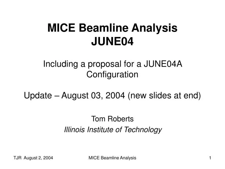
MICE Beamline Analysis JUNE04 Including a proposal for a JUNE04A Configuration Update – August 03, 2004 (new slides at end). Tom Roberts Illinois Institute of Technology. JUNE04 Beamline Design. Same basic physical layout as MAR04, with minor changes (e.g. downstream iron shield)

E N D
MICE Beamline AnalysisJUNE04Including a proposal for a JUNE04A ConfigurationUpdate – August 03, 2004 (new slides at end) Tom Roberts Illinois Institute of Technology MICE Beamline Analysis
JUNE04 Beamline Design • Same basic physical layout as MAR04, with minor changes (e.g. downstream iron shield) • Corrects many deficiencies of earlier designs • JUNE04 still has problems: • Beam distributions are not all as desired (see below) • TOF0 singles rate is ~10 MHz • Good mu+ rate is less than half of the desired 600 ev/sec • This talk discusses my analysis of a number of suggestions to address these problems. • I propose a JUNE04A design that both reduces the TOF0 singles rate and increases the good mu+ rate MICE Beamline Analysis
JUNE04 Layout ISIS Beam TOF0 TOF1 Diffuser Iron Shield TOF2 Ckov2Cal Ckov1 MICE Beamline Analysis
JUNE04 Beamline Design – Properties MICE Beamline Analysis
Observations on overall beam distributions, JUNE04 ☺ Average Momentum After Diffuser: 250MeV/c => ~ 236.5MeV/c Good for Amplitude vs p correlation Narrow-momentum (+/-1% ~ 236.5MeV/c): Beam OK ☺ Narrow-momentum Beam OK xx' larger distribution (improvable with quad optics) Narrow momentum region yy' 6pi & well matched Overall beam distribution: Suffers from a few aberrations Full beam Still needs attention xx' large distribution, <x> ≠ 0 & not well matched yy' ≥10pi & not well matched Peak Momentum > 236.5MeV/c ! 236.5MeV/c MICE Beamline Analysis
Suggested Improvements • Raise the pion momentum in the beamline • improve π/μ separation in B2 • Reduce TOF0 singles by eliminating πs • Slight increase in pion production • Move TOF0 downstream of Q5, or downstream of Q6 • Reduce TOF0 singles • Reduce effect of multiple scattering in TOF0 • Requires moving TOF1 downstream of Q9, and an analysis that the pi/mu discrimination is still OK (below) • Use thinner counters for TOF0 and TOF1 • Reduce effect of multiple scattering in TOF0 and TOF1 • Consider changing the tune from FDF in Q4-6 to DFD • Steer more pions into the Q4 iron, and away from TOF0 • Perhaps also DFD in Q7-9 • May be able to better balance the vertical and horizontal emittances (better horizontal aperture control of the beam?) • Included in this analysis and proposal for JUNE04A MICE Beamline Analysis
Evaluation Criteria • At present we don’t know the targeting parameters we will achieve, and basically must make an educated guess of what the overall rates will be. • In practice, the target will have an adjustable insertion depth into the ISIS beam, and we will insert it until we are limited by one of the following: • ISIS beam losses / activation of beamline elements • Target heating • Singles in TOF0 • Tracker or DAQ event rate capacity • The beamline design and tune cannot affect A, B, or D, and can only hope to optimize the good mu+ rate relative to TOF0 singles. The criteria I have used is to maximize the good-μ+ rate and to minimize TOF0/good-μ+, both for a given set of 10M target π+. Remarkably, these two criteria are compatible. MICE Beamline Analysis
Proposed JUNE04A Layout Pπ = 425 MeV/c Moved, Thinner, TOF0 Moved, Thinner, TOF1 New Iron Shield (TOF1 and its iron shield are symmetrical with TOF2, except for the Diffuser) MICE Beamline Analysis
Comparison of JUNE04 and Proposed JUNE04A [1] π/μ/e discrimination in TOF1-TOF0 presented below. [2] Narrow-momentum beam, no multiple-scattering from TOF0 and TOF1, horizontal emittance much larger. Reasonably consistent with ecalc9 value. MICE Beamline Analysis
JUNE04A π/μ/e Discrimination in TOF1-TOF0 • A major change in the JUNE04A design is the reduction in distance between TOF0 and TOF1, so we must verify that π+ can still be cleanly separated from μ+ • There are no protons – TOF0 stops >99% of them in this momentum range • Using Tracker1 to measure Ptot, the perfect-resolution graph looks fine: Perfect TOF and Tracker Resolution • A Q4-filling Gaussian beam with equal numbers of π+, μ+ and e+ • No correction for Eloss in the Diffuser • GoodParticle = TOF0 & TOF1 & Tracker1 • Still present: • Variations in path length • Variations in Eloss (Diffuser) MICE Beamline Analysis
Estimated TOF and Tracker Resolutions • From the proposal, TOF0 and TOF1 are estimated to have resolutions of 50 ps, giving a resolution of 70.7 ps for TOF1-TOF0. • From the proposal, Tracker1 is estimated to have a resolution in Pperp of 0.12 MeV/c. • The resolution in Pz depends strongly on Pperp, and is given in Fig 3.9 of the proposal; it is modeled here: MICE Beamline Analysis
JUNE04A π/μ/e Discrimination, with Estimated Gaussian Resolutions in Pperp, Pz, and TOF MICE Beamline Analysis
Conclusions about JUNE04A • Straightforward modifications to JUNE04 provide significant improvements in performance: • TOF0 singles reduced by a factor of ~2.5 • Good μ+rate increased by a factor of ~1.5 • Input emittance slightly reduced • The reduction in TOF0 to TOF1 distance is OK – we still have good π/μ/e discrimination • Reducing TOF0 and TOF1 to 1 inch total thickness improves the rate of good μ+ • Still need a design iteration: • Improve horizontal distributions • Correct the overall emittance • Tune the Decay Solenoid field (better π focusing and separation from μ) MICE Beamline Analysis
Comment on MICE Targeting Current Baseline Possible Change ISIS Beam • There clearly is a multiple-scattering angle, and an energy loss, below which protons intersecting the target will not be lost. • Because of this, it may be appropriate to rotate the target 90 degrees, so it is 10 mm wide and 1mm in length. • While ~10 times more protons will intersect the target, perhaps only those that strongly interact will be lost. • With everything else equal, we will adjust the depth so the number of strongly-interacting protons will be the same, independent of orientation. • This might reduce ISIS losses, while not significantly affecting either the target heating or the MICE muon rates. ISIS Beam Ti Ti 1 mm wide, 10 mm thick, variable depth 10 mm wide, 1 mm thick, variable depth MICE Beamline Analysis
Comparison of 1mm and 10mm Target Thicknesses Multiple Scattering Energy Loss • Clearly the 1mm-thick orientation has much less impact on individual ISIS protons than does the 10mm-thick orientation. • Evaluating whether or not this target rotation will reduce ISIS losses requires an analysis using the ISIS beam properties and lattice. MICE Beamline Analysis
Update August 03, 2004 • I was asked to provide three updates: • An analysis of TOF1-TOF0 pi/mu separation, moving just TOF0 (i.e. TOF1 remains between Q8 and Q9), fixing the resolution in Pperp. • A histogram of TOF1-TOF0 timing for a narrow momentum cut. • The evaluation matrix I used to determine the basic features of JUNE04A • In the process, I discovered two errors in the original presentation – both had the effect of making JUNE04A look like less of an improvement that it really is: • For JUNE04 ev/sec, I transcribed (excel=>powerpoint) the momentum (350) instead of the ev/sec (261) • I used the selected entry in my evaluation matrix for JUNE04A, rather than the correct JUNE04A – the matrix had TOF1 between Q8 and Q9 (note the TOF1-TOF2 analysis had TOF1 located correctly, after Q9) • I have made the corrections above, highlighted in red MICE Beamline Analysis
TOF1-TOF2, TOF0 after Q6, TOF1 after Q8 NOTE: There is 1 pi+ event that is close to the mu+ band. This is NOT a pi+ decay (decays are disabled). MICE Beamline Analysis
TOF1-TOF2, ComparisonJUNE04A (except TOF1 position) TOF1 after Q8 No Upstream Iron Shield TOF1 after Q9 With Upstream Iron Shield Note the different time scales (y axis) σ(Pperp) = 0.12 MeV/c (should be 3 MeV/c – see below) MICE Beamline Analysis
TOF1-TOF0, 290 < Ptot(meas) < 300 MeV/c σ(Pperp) = 0.12 MeV/c (should be 3 MeV/c – see below) MICE Beamline Analysis
TOF1-TOF2, Comparison of σ(Pperp) valuesJUNE04A (except TOF1 between Q8 and Q9) σ(Pperp) = 0.12 MeV/c σ(Pperp) = 3.0 MeV/c Note: for σ=3.0 there are a few more pi and mu in “no-man’s land”. I’m a bit surprised there was so little change in the plot. MICE Beamline Analysis
Evaluation Matrix - 1 TOF0 located after the Quad in the column heading. TOF1 located between Q8 and Q9. JUNE04A value (TOF1 moved after Q9, add upstream Iron Shield): 6.5 MICE Beamline Analysis
Evaluation Matrix - 2 TOF0 located after the Quad in the column heading. TOF1 located between Q8 and Q9. JUNE04A values (TOF1 moved after Q9, add upstream Iron Shield): TOF0 singles: 3831 good-mu: 591 MICE Beamline Analysis