Download
1 / 18
180 likes | 307 Views
Front End Test Stand Klystron Commissioning Alan Letchford UKNF Plenary Meeting 22 nd April 2009. The Front End Test Stand (FETS) aims to demonstrate key technologies for the front end of the next generation of high power pulsed proton accelerators. Applications include:

E N D
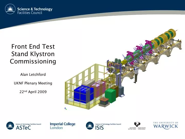
Front End Test Stand Klystron Commissioning Alan Letchford UKNF Plenary Meeting 22nd April 2009
The Front End Test Stand (FETS) aims to demonstrate key technologies for the front end of the next generation of high power pulsed proton accelerators. • Applications include: • UK Neutrino Factory • ISIS upgrades • Future Spallation Neutron Sources • Waste Transmutation • ADS etc • The key components of FETS are: • High intensity, high duty factor, H- ion source • Magnetic Low Energy Beam Transport (LEBT) • 324 MHz 4-vane Radio Frequency Quadrupole (RFQ) • Medium Energy Beam Transport (MEBT) • Very high speed beam chopper • Comprehensive diagnostics • FETS is a collaboration between ISIS, ASTeC, Imperial College London, Warwick University and the University of the Basque Country in Spain.
A big challenge for all future MW scale proton accelerators is controlling beam loss. Beam loss leads to component activation – component activation hinders hands-on maintenance. Absolute loss levels in the future machines (1 – 10 MW beam power) must be similar to that on ISIS (160 kW beam power). Fractional loss must therefore be reduced by orders of magnitude. A significant reduction in beam loss in circular accelerators can be achieved by chopping the beam in the injector linac so as to precisely fill the ring RF bucket – no trapping loss and much reduced extraction loss. ‘Perfect’ chopping is extremely challenging. One of the main focuses for FETS is to demonstrate perfect chopping on a full power beam.
Chopping will be demonstrated on a 3 MeV H- beam delivered by the FETS RFQ. A frequency of 324 MHz has been chosen due to the availability of RF power at this frequency. The alternative possibility of 405 MHz makes perfect chopping more difficult. The 4m long RFQ will need 6-700 kW of structure power and about 175 kW for the beam. Total RF requirement is ~1MW, up to 50pps and 2ms pulses.
The chosen RF power source is a Toshiba E3740A klystron as used on the J-PARC linac. Due to the low frequency and high power it is a very large device.
~5m long, ~3 tonnes. 3MW max peak power, 80kW max average window power Modulating anode 110kV cathode potential, 50A peak beam current
A fully solid state power supply and modulator has been purchased from Diversified Technologies Inc of Boston, USA Due to the high power and voltage this is also quite large.
The system consists of an autotransformer, 2 switching power supplies, a capacitor bank , solid state switch, floating heater power supply and modulating anode power supply. Total weight ~9 tonnes – before being filled with ~7000l of oil.
A dummy load and waveguide system including directional coupler and arc detector was supplied by Mega Industries. Temperature controlled ethylene glycol load. This proved to be the least reliable part of the system. But it was cheap!
Due to the klystron being the only suitable load for the power supply, the system had to be commissioned as a whole. All components had previously undergone full power factory tests. One week was scheduled for commissioning with engineers from Toshiba and diversified. 3 days were spent making all the interconnects and high voltage terminations, filling both klystron and modulator with oil and testing interlocks.
During the first day of running 70kV, 10pps, 250µs pulses were delivered to the klystron. There were no signs of breakdowns or vacuum rises so RF was gradually applied to the input. ~600kW @ 10pps & 250µs was achieved. On Good Friday the voltage was increased to 95kV and 1MW @ 30pps & 1ms pulses was achieved before problems with the dummy load halted proceedings. Not a single HV breakdown or waveguide arc was detected. Some low level x-rays were detected around the collector and window.
Multiple problems with the dummy load limited progress towards full FETS operating conditions: Overheating motor Leaking pump seal Faulty flow switch Blocked heat exchanger Although frustrating these are relatively trivial problems to fix but there was no time before the teams from Toshiba and Diversified returned home. The load will be fixed and some temporary aspects of the installation made permanent before running again.
Summary Over 1 week in early April the FETS klystron and PSU/modulator were successfully commissioned to close to full power. 1MW, 30pps, 1ms were achieved with remarkable ease. Limiting factor was the poorly designed cooling circuit on the high power glycol load. Both the Toshiba klystron and the Diversified PSU/modulator appear to be high quality pieces of equipment. The installation will now be made permanent and the x-ray shielding improved before further long term running is attempted.