Download
1 / 66
660 likes | 743 Views
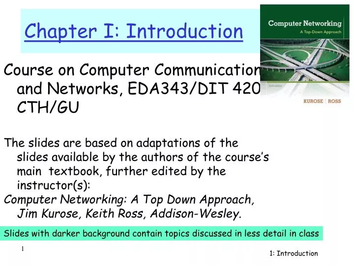
Course on Computer Communication and Networks , EDA343/DIT 420, CTH/GU The slides are based on adaptations of the slides available by the authors of the course’s main textbook , further edited by the instructor (s):

E N D
Course on Computer Communication and Networks, EDA343/DIT 420, CTH/GU The slidesarebased on adaptations of the slidesavailable by the authorsof the course’smaintextbook, furtheredited by the instructor(s): Computer Networking: A Top Down Approach,Jim Kurose, Keith Ross, Addison-Wesley. Chapter I: Introduction Slideswithdarkerbackgroundcontaintopicsdiscussed in less detail in class 1: Introduction
Overview: what’s the Internet types of service ways of information transfer, routing, performance, delays, loss -------------------------------------------- protocol layers, service models access net, physical media backbones, NAPs, ISPs (history) quick look into ATM networks Chapter I: Introduction 1: Introduction
millions of connected computing devices: hosts = end systems running network apps PC Mobile network server Global ISP wireless laptop cellular handheld Home network Regional ISP access points wired links Institutional network router the Internet: “nuts and bolts” view • communication links • fiber, copper, radio, satellite • transmission rate = bandwidth • routers: forward packets (chunks of data) Introduction
protocolscontrol sending, receiving of msgs e.g., TCP, IP, HTTP, Skype, Ethernet Internet: “network of networks” loosely hierarchical public Internet versus private intranet Internet standards RFC: Request for comments IETF: Internet Engineering Task Force Mobile network Global ISP Home network Regional ISP Institutional network the Internet: “nuts and bolts” view Introduction
communication infrastructure enables distributed applications: Web, VoIP, email, games, e-commerce, file sharing communication services provided to apps: reliable data delivery from source to destination “best effort” (unreliable) data delivery the Internet: a service view Introduction
Internet standards • RFC: Request for comments • IETF: Internet Engineering Task Force 1: Introduction
network edge: applications and hosts A closer look at (any big)network’s structure: • access networks, physical media: wired, wireless communication links • network core: • interconnected routers • network of networks Introduction
end systems (hosts): run application programs e.g. in Internet Web, email, … … based on network services available at the edge peer-peer client/server The network edge: • types of service offered by the network to applications: • connection-oriented: deliver data in the order they are sent • connectionless: delivery of data in arbitrary order Introduction
mesh of interconnected routers fundamental question: how is data transferred through net? packet-switching: data sent thru net in discrete “chunks” We will contrast with circuit switching: dedicated circuit per call: “classic”phone net The Network Core Introduction
NetworkCore 1: Introduction
D E Network Core: Packet Switching 10 Mbs Ethernet C A statistical multiplexing 1.5 Mbs B queue of packets waiting for output link 45 Mbs 1: Introduction
each end-end data stream divided into packets packets share network resources resources used as needed store and forward: packets move one hop at a time transmit over link wait turn at next link http://www.youtube.com/watch?v=O7CuFlM4V54 Watch the video at home; nice animation; disregard the terms used in narration; they do not follow exact protocol specifications Network Core: Packet Switching resource contention: • aggregated resource demand can exceed amount available (bandwidth) , hence … • … congestion: packets queue, wait for link use 1: Introduction
packets experience delay on end-to-end path 1. nodal processing: check bit errors determine output link 2. queuing time waiting at output link for transmission depends on congestion level of router transmission A propagation B nodal processing queueing Delay in packet-switched networks • http://www.youtube.com/watch?v=O7CuFlM4V54 • Nice animation; disregard the terms used in narration; they do not follow exact protocol specifications 1: Introduction
3. Transmission delay: R=link bandwidth (bps) L=packet length (bits) time to send bits into link = L/R 4. Propagation delay: d = length of physical link s = propagation speed in medium (~2x10⁸ m/sec) propagation delay = d/s transmission A propagation B nodal processing queuing Delay in packet-switched networks Note: s and R are very different quantities! 1: Introduction
store and forward behavior + other delays’ visualization (fig. from “Computer Networks” by A. Tanenbaum,) Visualize deleys: Circuit, message, packet switching 1: Introduction
End-end resources reserved/dedicated for “call” link bandwidth, switch capacity dedicated resources: no sharing circuit-like (guaranteed) performance call setup required Network Core: Circuit Switching Introduction
1 Mbit link each user: 100Kbps when “active” active 10% of time (bursty behaviour) circuit-switching: 10 users packet switching: with 35 users, probability > 10 active less than 0.0004 ( almost all of the time same queuing behaviour as circuit switching) Packet switching allows more users to use the network! Packet switching versus “classical” circuit switching N users 1 Mbps link 1: Introduction
R=link bandwidth (bps) L=packet length (bits) a=average packet arrival rate Queueing delay (revisited) … traffic intensity = La/R • La/R ~ 0: average queueing delay small • La/R -> 1: delays become large • La/R > 1: more “work” arriving than can be serviced, average delay infinite! Queues may grow unlimited, packets can be lost 1: Introduction
… “Real” Internet delays and routes (1)… • What do “real” Internet delay & loss look like? • Traceroute program: provides delay measurement from source to router along end-end Internet path towards destination. For all i: • sends three packets that will reach router i on path towards destination • router i will return packets to sender • sender times interval between transmission and reply. 3 probes 3 probes 3 probes 1: Introduction
…“Real” Internet delays and routes (2)… traceroute: gaia.cs.umass.edu to www.eurecom.fr Three delay measurements from gaia.cs.umass.edu to cs-gw.cs.umass.edu 1 cs-gw (128.119.240.254) 1 ms 1 ms 2 ms 2 border1-rt-fa5-1-0.gw.umass.edu (128.119.3.145) 1 ms 1 ms 2 ms 3 cht-vbns.gw.umass.edu (128.119.3.130) 6 ms 5 ms 5 ms 4 jn1-at1-0-0-19.wor.vbns.net (204.147.132.129) 16 ms 11 ms 13 ms 5 jn1-so7-0-0-0.wae.vbns.net (204.147.136.136) 21 ms 18 ms 18 ms 6 abilene-vbns.abilene.ucaid.edu (198.32.11.9) 22 ms 18 ms 22 ms 7 nycm-wash.abilene.ucaid.edu (198.32.8.46) 22 ms 22 ms 22 ms 8 62.40.103.253 (62.40.103.253) 104 ms 109 ms 106 ms 9 de2-1.de1.de.geant.net (62.40.96.129) 109 ms 102 ms 104 ms 10 de.fr1.fr.geant.net (62.40.96.50) 113 ms 121 ms 114 ms 11 renater-gw.fr1.fr.geant.net (62.40.103.54) 112 ms 114 ms 112 ms 12 nio-n2.cssi.renater.fr (193.51.206.13) 111 ms 114 ms 116 ms 13 nice.cssi.renater.fr (195.220.98.102) 123 ms 125 ms 124 ms 14 r3t2-nice.cssi.renater.fr (195.220.98.110) 126 ms 126 ms 124 ms 15 eurecom-valbonne.r3t2.ft.net (193.48.50.54) 135 ms 128 ms 133 ms 16 194.214.211.25 (194.214.211.25) 126 ms 128 ms 126 ms 17 * * * 18 * * * 19 fantasia.eurecom.fr (193.55.113.142) 132 ms 128 ms 136ms trans-oceanic link * means no reponse (probe lost, router not replying) 1: Introduction
PS: Good: Great for bursty data resource sharing no call setup PS: Not so good? Excessive congestion: packet delay and loss protocols needed for reliable data transfer, congestion control http://www.youtube.com/watch?v=Dq1zpiDN9k4&feature=related Q: How to provide circuit-like behavior? bandwidth guarantees needed for audio/video apps Some routing policies can help (cf next slide) Packet switching properties 1: Introduction
Goal: move packets among routers from source to destination Challenge 1: path selection algorithms Challenge2: Important design issue: datagram network: destination address determines next hop routes may change during session virtual circuit network: each packet carries tag (virtual circuit ID), tag determines next hop fixed path determined at call setup time, remains fixed thru call routers maintain per-call state Packet-switched networks: routing 1: Introduction
“source-to-dest path behaves almost like a circuit” call setup, teardown for each call before data can flow signaling protocols to setup, maintain, teardown VC everyrouter maintains “state” for each passing connection resources (bandwidth, buffers) may be allocated to VC application transport network data link physical application transport network data link physical Virtual circuits: 6. Receive data 5. Data flow begins 4. Call connected 3. Accept call 1. Initiate call 2. incoming call
Packet-switched networks Circuit-switched networks Datagram Networks Networks with VCs Network Taxonomy Telecommunication networks • Datagram network (eg Internet) cannot be characterized either connection-oriented or connectionless. • Internet provides both connection-oriented (TCP) and • connectionless services (UDP), at the network edge, to apps. 1: Introduction
Packet loss • queue (aka buffer) preceding link has finite capacity • packet arriving to full queue dropped (aka lost) • lost packet may be retransmitted by previous node, by source end system, or not at all buffer (waiting area) packet being transmitted A B packet arriving to full bufferis lost Introduction
pipe that can carry fluid at rate Rsbits/sec) pipe that can carry fluid at rate Rcbits/sec) Throughput • throughput: rate (bits/time unit) at which bits transferred between sender/receiver • instantaneous: rate at given point in time • average: rate over longer period of time link capacity Rcbits/sec link capacity Rsbits/sec server, with file of F bits to send to client server sends bits (fluid) into pipe Introduction
Rs > RcWhat is average end-end throughput? Rsbits/sec Rcbits/sec Rcbits/sec bottleneck link link on end-end path that constrains end-end throughput Throughput (more) • Rs < RcWhat is average end-end throughput? Rsbits/sec Introduction
Throughput: Internet scenario • per-connection end-end throughput: min(Rc,Rs,R/10 (if fair)) • in practice: Rc or Rs is often bottleneck Rs Rs Rs R Rc Rc Rc 10 connections (fairly) share backbone bottleneck link Rbits/sec Introduction
Access networks and physical media 1: Introduction
Q: How to connect end systems to edge router? residential access nets institutional access networks (school, company) mobile access networks Keep in mind: bandwidth (bits per second) of access network? shared or dedicated? Access networks and physical media 1: Introduction
Dial-up Modem central office telephone network Internet homedial-up modem ISPmodem (e.g., AOL) home PC • Uses existing telephony infrastructure • Home is connected to central office • up to 56Kbps direct access to router (often less) • Can’t surf and phone at same time: not “always on”
telephone network Digital Subscriber Line (DSL) Internet Existing phone line: home phone DSLAM splitter DSL modem Central Office: multiplexer home PC • Also uses existing telephone infrastruture • Commonly up to 2.5 Mbps upstream (more typically < 1 Mbps) • Commonly up to 24 Mbps downstream (more typically < 10 Mbps) • dedicated physical line to telephone central office
cable modem termination system data, TV transmitted at different frequencies over shared cable distribution network ISP Access net: cable network cable headend … cable modem splitter CMTS • HFC: hybrid fiber coax • asymmetric: up to 30Mbps downstream transmission rate, 2 Mbps upstream transmission rate • network of cable, fiber attaches homes to ISP router • homes share access networkto cable headend • unlike DSL, which has dedicated access to central office Introduction
company/univlocal area network (LAN) connects end system to edge router E.g. Ethernet: shared or dedicated cable connects end system and router 10 Mbs, 100Mbps, Gigabit Ethernet deployment: institutions, home LANs Institutional access: local area networks 1: Introduction
shared wireless access network connects end system to router via base station aka “access point” wireless LANs: 802.11b/g (WiFi): 11 or 54 Mbps wider-area wireless access provided by telco operator ~1Mbps over cellular system next up (?): WiMAX (10’s Mbps) over wide area Wireless access networks router base station mobile hosts Introduction
Typical home network components: DSL or cable modem router/firewall/NAT Ethernet wireless access point Home networks wireless devices to/from cable headend Cable or DSL modem router/ Firewall NAT wireless access Point (54 Mbps) Ethernet 1: Introduction
physical link: transmitted data bit propagates across link guided media: signals propagate in solid media: copper, fiber unguided media: signals propagate freely e.g., radio Physical Media 1: Introduction
signal carried in electromagnetic spectrum Omnidirectional: signal spreads, can be received by many antennas Directional: antennas communicate with focused el-magnetic beams and must be aligned (requires higher frequency ranges) propagation environment effects: reflection obstruction by objects interference Physical media: wireless 1: Introduction
Properties: Attenuation, Multipath propagation Signal can fade with distance, can get obstructed, can take many different paths between sender and receiver due to reflection, scattering, diffraction signal at sender signal at receiver
Twisted Pair (TP) two insulated copper wires Category 3: traditional phone wires, 10 Mbps Ethernet Category 5 TP: more twists, higher insulation: 100Mbps Ethernet Physical Media: Twisted pair 1: Introduction
Coaxial cable: wire (signal carrier) within a wire (shield) baseband: single channel on cable (common use in 10Mbs Ethernet) broadband: multiple channels on cable (FDM; commonly used for cable TV) Physical Media: coax, fiber Fiber optic cable: • glass fiber carrying light pulses • low attenuation • high-speed operation: • 100Mbps Ethernet • high-speed point-to-point transmission (e.g., 5 Gps) • low error rate 1: Introduction
Back to Layers-discussion 1: Introduction
Networks are complex! many “pieces”: hosts routers links of various media applications protocols hardware, software Question: Is there any hope of organizing structure of network? Or at least our discussion of networks Protocol “Layers” 1: Introduction
Why layering? Dealing with complex systems: • explicit structure allows identification, relationship of complex system’s pieces • layered reference model for discussion • modularization eases maintenance/es • change of implementation of layer’s service transparent to rest of system • e.g., change in gate procedure doesn’t affect rest of system 1: Introduction
Terminology: Protocols, Interfaces • Each layer offersservicesto the upper layers (shielding from the implementation details) • service interface: acrosslayers in same host • Layer n on a host carries a conversation with layer n on another host • PROTOCOL, host-to-hostinterface: defines messages exchanged with peerentity • Network architecture(set of layers, interfaces) vsprotocol stack (protocol implementation) 1: Introduction
a human protocol and a computer network protocol: TCP connection reply. Get http://gaia.cs.umass.edu/index.htm Got the time? 2:00 <file> time What’s a protocol? Hi TCP connection req. Hi host-to-hostinterface: defines messages exchanged with peerentity: format, order of msgs sent and received among network entities and actions taken on msg transmission, receipt 1: Introduction
The OSI Reference Model • ISO (International Standards Organization) defines the OSI (Open Systems Inerconnect) model to help vendors create interoperable networkimplementation • Reduce the problem into smaller and more manageable problems: 7 layers • a layer should be created where a different level of abstraction is needed;each layer should perform a well defined function) • The function of each layer should be chosen with an eye toward defininginternationally standardized protocols • ``X dot" series (X.25, X. 400, X.500) OSI model implementation(protocol stack) 1: Introduction
application: ftp, smtp, http, etc transport:tcp, udp, … network:routing of datagrams from source to destination ip, routing protocols link: data transfer between neighboring network elements ppp, ethernet physical: bits “on the wire” application transport network link physical Internet protocol stack 1: Introduction
Internet protocol stack • Architecture simple but not as good as OSI‘s • no clear distinction between interface-design and implementations; • hard to re-implement certain layers • Successful protocol suite (de-facto standard) • was there when needed (OSI implementations were too complicated) • freely distributed with UNIX 1: Introduction
Each layer: distributed “entities” implement layer functions at each node entities perform actions, exchange messages with peers network link physical application transport network link physical application transport network link physical application transport network link physical application transport network link physical Layering: logical communication 1: Introduction