Download
1 / 34
430 likes | 662 Views
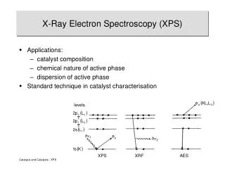
X RAY SPECTROSCOPY. Introduction. X-rays are a part of electromagnetic spectrum. X-rays have a wavelength in ranges of 0.01nm to 10nm.70-200pm for (AP). Produced by the deceleration of high-energy electrons. Electronic transition of electrons in the inner orbitals of atoms.

E N D
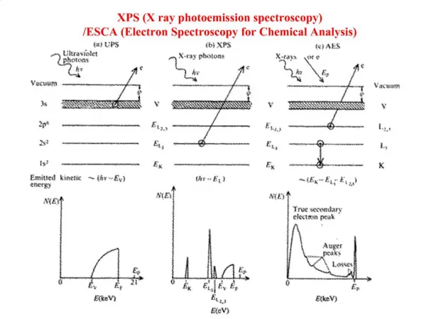
Introduction • X-rays are a part of electromagnetic spectrum. • X-rays have a wavelength in ranges of 0.01nm to 10nm.70-200pm for (AP). • Produced by the deceleration of high-energy electrons. • Electronic transition of electrons in the inner orbitals of atoms.
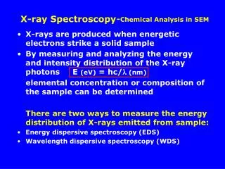
X RAY CHARACTERSTICS ABSORBTION X rays give information about the absorbing material just. Like other regions of the electromagnetic spectrum X rays are absorbed by matter and degree of absorbtion is determined by the nature and amount of absorbing material.
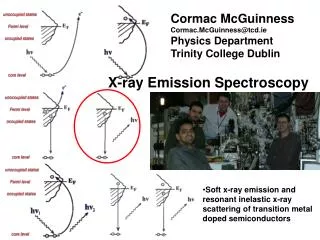
FLUORESCENCE Fluorescence emission of X-rays enables to identify and measure heavy elements. It is used for quantitative and qualitative determination of heavy elements DIFFRACTION Diffraction of x rays is used in analysis of crystalline materials with high degree of accuracy and specificity.
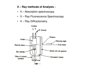
INSTRUMENTATION FOR X-RAY SPECTROSCOPY Components for X-ray spectroscopy are : • X-ray generating equipment (X-ray tube) • Collimator • Monochromators • detectors
X-Ray Tube Determining the energy of the X-Ray 100KV! Controlling the intensity of X-Ray
(1) X-Ray Tube (2) Collimators A collimator is a device that narrows a beam of particles or waves. Narrow mean to cause the directions of motion to become more aligned in a specific direction (i.e., collimated or parallel). Collimation is achieved by using a series of closely spaced ,parallel metal plates or by a bundle of tubes ,0.5 or less in diameter. • X-rays can be generated by an X-ray tube. • X-rays tube is a vacuum tube that uses a high voltage to accelerate the electrons released by a hot cathode to a high velocity. • The high velocity electrons collide with a metal target, the anode, creating the X-rays.
Monochromator • Need of Monochromator • Types of Monochromator • Working of Filters • Filter v/s Monochromator • Working of diffraction grating • Advantages of monochrome X-Rays
Need of Monochromator • Monochromator crystals partially polarize an unpolarized X-ray beam • The main goal of a Monochromator is to separate and transmit a narrow portion of the optical signal chosen from a wider range of wavelengths available at the input. Monochromators
Types of Monochromator • Metallic Filter Type • Diffraction grating type
Working of Filters • Filters exploit the X-ray absorption edge of the particular element. • At wavelengths longer than the absorption edge (i.e. just above the edge), the absorption of the X-rays is considerably less than for wavelengths shorter than the absorption edge (i.e. just below the edge) as shown for nickel metal:
Working of Filters • The absorption edge of nickel metal at 1.488 Å lies between the Kα (λ = 1.542 Å) and Kβ (λ = 1.392 Å) X-ray spectral lines of copper. Hence nickel foil of an appropriate thickness can be used to reduce the intensity of the Cu Kβ X-rays as shown:
Choice of filter metal • The choice of filter material depends upon the choice of anode material in the X-ray tube as shown in the following table:
Laboratory X-ray Filters • The beam passes through the top filter which in this case is a nickel foil. Alternative metal foils can be set by rotation of the filter housing to the appropriate position • One position on the filter housing is left open for the case when a filter is not required.
Limitations of Filter • X-ray filters were used to reduce the unwanted white radiation from the X-ray source and to eliminate (as much as possible) the Kβ radiation. • The drawback of filters is that the background radiation is still high and that the transmitted radiation is still not very monochromatic.
Working of diffraction grating • Source (A) • Entrance slit (B) • Collimator(C) • Grating (D) • Another mirror (E) • Exit slit (F)
Advantages of monochrome X-Rays • Improved resolution • Minimizing sample damage • Improved signal to noise ratio • Analyze of small samples • Multispotting on samples • Simplified data processing
X-ray Detectors • Solid State Detectors • Scintillation Detectors • Gas-filled Detectors
Solid State Detectors X-ray
Solid State Detectors • The charge carriers in semiconductor are electrons and holes. • Radiation incident upon the semiconducting junction produces electron-hole pairs as it passes through it. Electrons and holes are swept away under the influence of the electric field, and the proper electronics can collect the charge in a pulse.
Photo Cathode Dynodes e- - HV e- + Scintillator Focusing cup Resistor Scintillation Detector
Scintillation detectors • Scintillation detectors consist of a scintillator and a device, such as a PMT(Photomultiplier tubes), that converts the light into an electrical signal • Consists of an evacuated glass tube containing a photocathode, typically 10 to 12 electrodes called dynodes, and an anode • Electrons emitted by the photocathode are attracted to the first dynode and are accelerated to kinetic energies equal to the potential difference between the photocathode and the first dynode
Scintillation detectors • When these electrons strike the first dynode, about 5 electrons are ejected from the dynode for each electron hitting it • These electrons are attracted to the second dynode, and so on, finally reaching the anode • Total amplification of the PMT is the product of the individual amplifications at each dynode • If a PMT has ten dynodes and the amplification at each stage is 5, the total amplification will be approximately 10,000,000 • Amplification can be adjusted by changing the voltage applied to the PMT
Gas-filled detectors • A gas-filled detector consists of a volume of gas between two electrodes, with an electrical potential difference (voltage) applied between the electrodes • Ionizing radiation produces ion pairs in the gas • Positive ions (cat-ions) attracted to negative electrode (cathode); electrons or anions attracted to positive electrode (anode) • In most detectors, cathode is the wall of the container that holds the gas and anode is a wire inside the container
+ e- (+) Anode Resistor (-) Cathode - + Battery or High Voltage Geiger Mueller Counter
Geiger Mueller Counter • GM counters also must contain gases with specific properties • Most common type of detector • Electrical collection of ions • When the gas amplification factor reaches 108, the size of the output pulse is a constant, independent of the initial energy deposit. • In this region, the Geiger- Mueller region, the detector behaves like a spark plug with a single large discharge. • Simple cheap electronics • Energy dependence • Large dead times, 100-300µs, result • No information about the energy of the radiation is obtained or its time characteristics.
X-ray Diffractometer • Diffraction is a phenomena of bending of light around the corners of an obstacle ,when the size of an obstacle is of the order of wavelength of light. • Wavelength of X-rays is of the order of few angstroms (10^-10m), same as inter-atomic distance in crystalline solids. • Thus, X-rays can be diffracted from minerals which are crystalline and have regularly repeating atomic structures. • Every crystalline substance will scatter the X-Rays in its own unique diffraction pattern. • According to Bragg's law n = 2d Sin where d= distance between similar atomic planes in mineral (inter-atomic spacing = angle of diffraction = wavelength n= an integer – 1,2,3.. etc (order of diffraction) • A diffractometer is a measuring instrument for analyzing the crystallographic structure of a material from the scattering (diffraction) pattern produced when a beam of radiation or particles (such as X-rays) interacts with it.
X-ray Diffractometer • A typical diffractometer consists of a source of radiation, a monochromator to choose the wavelength, collimator to make the beam parallel, a sample and a detector. • An x-ray diffractometer illuminates a sample of material with x-rays of known wavelength. • A strip of X-Ray film is mounted in circular position around the sample. • The undeviated central beam passes out through a hole E cut in the film strip P. Diffracted beam falls on the film at various points like d1, d2, d3 etc. • Intensities of the diffraction peaks are proportional to the fraction of the material in the mixture.
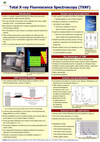
X-ray Fluorescence Spectrometry • Re-emission of light of different wavelength is called fluorescence. • Advantage of fluorescence detection over absorption is greater sensitivity. • Fluorescence is more selective then absorption due to fact that all molecule that fluoresce must absorb, but not all molecules that absorb necessarily fluoresce. XRF is capable of measuring elements from beryllium (Be) to uranium (U). • XRF is a powerful tool for qualitative and quantitative determination of heavy metal.