Download
1 / 12
120 likes | 245 Views
Dilatancy /Compaction and Slip Instabilities of Fluid Infiltrated Faults. Vahe Gabuchian GE169B/277 01/25/2012 Dr. Lapusta Dr. Avouac. Experimental results of frictional behavior for porous materials Constitutive equations stemming from experimental observations

E N D
Dilatancy/Compaction and Slip Instabilities of Fluid Infiltrated Faults Vahe Gabuchian GE169B/277 01/25/2012 Dr. Lapusta Dr. Avouac • Experimental results of frictional behavior for porous materials • Constitutive equations stemming from experimental observations • 1-DOF spring slider system used as the model for the problem setup • Derivation of the lumped parameter set of equations describing the system • How does proposed model compare to the experimental results? • Linearized stability analysis and it’s significance • Implications for nucleation of earthquakes List of references used Dilatancy, compaction, and slip instability of a fluid-infiltrated fault, Segall, P. and Rice, J.R.,Journal of Geophysical Research, Vol. 100, No. B11, Pages 22,155-22,171, November 10, 1995. Dilatant strengthening as a mechanism for slow slip events, Segall, P., Rubin, A.M., Bradley, A.M., and Rice, J.R., Journal of Geophysical Research, Vol. 115, B12305, 2010. Frictional behavior and constitutive modeling of simulated fault gouge, Marone, C., Raleigh, C.B., and Scholz, C.H., Journal of Geophysical Research, Vol. 95, No. B5, Pages 7007-7025, May 10, 1990. Creep, compaction and the weak rheology of major faults, Sleep, N.H. and Blanpied, M.L., Nature, Vol. 359, 22 October, 1992, Pages 687-692. An earthquake mechanism based on rapid sealing of faults, Blanpied, M.L., Lockner, D.A., and Byerlee, J.D., Nature, Vol. 358, 13 August, 1992, Pages, 574-576.
Fault Gouge Experiments Link Frictional Resistance μ and Porosity ϕ Experiments on dilatancy and compaction of Marone, et al, apply step changes to load velocity (up/down) and measure porosity (cylinder height) and friction coefficient. • Frictional coefficient and porosity evolve to steady state values (μμss and ϕϕss) • Step increase in velocity promotes dilatancy, step decrease promotes compaction • The evolution length scale is approximately the same suggests physics are related • Higher loads shift porosity and frictional coefficient up to higher values
Constitutive Equations Based on Experimental Observation Needto model porosity changes with changes in system parameters (i.e. slip velocity, etc) Approach 1 Approach 2 • ϕis a function of slip velocityv(coming from the “critical state concept” in soil mechanics where a steady state value is postulated) • vϕandvϕ • Introducing the dilatancy coefficient, ε • Assume that steady state porosity varies as a function of state variable θrather than velocity • Same length scale, dc, makes proposed form physically reasonable Dilatancy coefficient Both approaches lead to models that are nearly identical but are exactly equal at steady state. Here we are only considering the plastic effects of porosity, elastic effects will be considered.
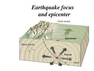
Model for Development of 1-DOF Spring Slider System Classic 1-DOF spring-slider model used to relate slip/slip rate u/v to system properties such as system stiffness,k, pore pressure,p, and frictional laws. The model is quasi- static: inertial effects are ignored (mass of block ignored). Frictional resistance (1) Driving force (2) Rate and State frictioncoefficient Frictional resistance depends on sliding velocity, v, and history of slip given by a state variable, θ. Allows for strengthening during no-slip conditions. (3) (4) Stability analysis has been done for this system with p = const (drained case). (5) Large stiffness (high k) favors stable sliding. High pore pressure (large p) favors stable sliding.
Governing Equations for Fluid: Linking Dilatancy, ϕ, to Pore Pressure, p Darcy’s law (1) (2) Conservation of mass (3) Evolution of fluid mass Compressibility of the fluid Distinguishing between elastic and plastic pore compressibility (elastic is only due to volumetric strains while plastic refers to irreversible volume changes due to shear motion) Neglecting poroelastic coupling Defining ELASTIC PORE COMPRESSIBILITY (4) Can write as A lumped parametermodel is derived by combining equations (4) (3) (2) (1). Assume the pressure to follow a simpler model and introduce a length scale, L Pore pressure satisfies diffusion equation in lumped parameter model with forcing term .
Full Set of Governing Equations System of 5 equations with 5 variables (1) (2) (3) Steady state values of variables are: (4) (5)
Model Agrees Well with Experimental Results of Marone, et. al. System of first order ODEs is solved numerically. • Step increase/decrease of v0 • (1 μm/s 10 μm/s 1 μm/s) • Confining eff. pressure of 150 MPa • a = 0.010 • b = 0.006 • dc = 0.02 mm • ε = 1.7e-4 • The two results (dashed and solid line) representtwo models of ϕ(Approach 1 and Approach 2). • The steady state solutions are exactly identical. • Small differences exist in the evolutionary portions in porosity and nearly no deviations in the frictional coefficient • Model and experimental results give a good qualitative and quantitative match
Stability Analysis of an Undrained System The drained case (p= const) has already been solved (Ruina’s spring slider model yields a kcrit and system stability behavior can be analyzed). Now allow pressure to be a system variable and perform a linear stability analysis for anundrainedsystem. Linearizethe system of equations about the steady state condition. At equilibrium Fspring= Ffric.resistance: Assume solutions of the form plug into the linearized equations, generate a characteristic equation for s, and solve for the roots. The systemhas stable slip if allRe(s) < 0 and unstable slip if any Re(s) > 0.
Linear Stability Analysis Results Similar to Ruina’s drained stability analysis, a kcrit is found and is given by Undrained Drained Value c* represents the ratio of permeability κ and the product of viscosity and the lumped parameter, υβ. The units of c* are ~1/t. The ratio v∞/dc is the inverse of θssis ~ 1/t. Thus ξ is the ratio of the characteristic time for state evolution to characteristic time for pore fluid diffusion. Note that if c* ∞, γ 0, and F(c*) 0 and recovers kcrit drained. For values of k slightly smaller than kcrit a velocity perturbation causes decaying oscillations in stress, sliding velocity, porosity, and pore pressure and the converse for values slightly larger than kcrit. Persistent oscillations exist for k = kcrit.
Numerical Simulations of Governing Equations • Results show that decaying oscillations exist for case A (k/kcrit = 1.05) Stable • Slowly growing sustained oscillations exist for case B (k/kcrit = 0.95) Limit cycle • Slowly growing sustained oscillations exist for case C (k/kcrit = 0.75) Limit cycle • Seeing larger magnitude sustained oscillations for case D (k/kcrit = 0.40) Limit cycle • Results show that oscillations rapidly increase for caseE (k/kcrit = 0.30) Unstable
Nucleation Size hcrit in a Continuum: Relation to kcrit Extending this 1-DOF spring-slider system to a continuum gives a feel of how the system spring stiffness, k, relates to the critical crack length, hcrit. τ The stiffness of a patch in a continuous media is given by: D Δδ The strain is proportional to: The change in shear stress goes as: h τ Drained case (p = const) • As p increases, (σ – p) decreases and hcrit increases • If hcrit is too large no instability can occur • Undrained case has even larger hcrit Undrained case (fluid trapped) In Sleep and Blanpied (1992) as pσ, (σ – p) 0 and hcrit ∞
Quantitative Analysis of hcrit • Sleep and Blanpied (1992)undrained case • Question: if we would like hcrit small enough, how small can (σ – p) be? • Using the values of parameters from Segall and Rice (1995)