Download
1 / 42
510 likes | 970 Views
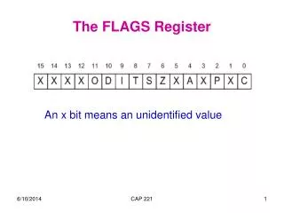
EFLAG Register of The 80486. The only new flag bit is the AC alignment check, used to indicate that the microprocessor has accessed a word at an odd address or a double word boundary . Signal Descriptions of 80386. Signal Descriptions of 80386.

E N D
EFLAG Register of The 80486 • The only new flag bit is the AC alignment check, used to indicate that the microprocessor has accessed a word at an odd address or a double word boundary.
Signal Descriptions of 80386 • CLK2 :The input pin provides the basic system clock timing for the operation of 80386. it is divided by two internally to generate the internal processor clock used for instruction execution. • D0 – D31:These 32 lines act as bidirectional data bus during different access cycles • A31 – A2: These are upper 30 bit of the 32- bit address bus. • BE0 toBE3(Byte/Bank enable) : The 32- bit data bus supported by 80386 and the memory system of 80386 can be viewed as a 4- byte wide memory access mechanism. The 4 byte enable lines BE0 to BE3 , may be used for enabling these 4 blanks. Using these 4 enable signal lines, the CPU may transfer 1 byte / 2 / 3 / 4 byte of data simultaneously.
Signal Descriptions of 80386 • ADS#(Address data strobe#): The address status output pin indicates that the address bus and bus cycle definition pins( W/R#, D/C#(Data/control#), M/IO#, BE0# to BE3# ) are carrying the respective valid signals. The 80383 does not have any ALE signals and so this signals may be used for latching the address to external latches. • READY#: The ready signals indicates to the CPU that the previous bus cycle has been terminated and the bus is ready for the next cycle. The signal is used to insert WAIT states in a bus cycle and is useful for interfacing of slow devices with CPU. • VCC: These are system power supply lines. • VSS: These return lines for the power supply.
M/IO#, D/C# and W/R# are decoded and generate the following signals.
Signal Descriptions of 80386 • BS16#(Bus Size#): The bus size – 16 input pin allows the interfacing of 16 bit devices with the 32 bit wide 80386 data bus. Successive 16 bit bus cycles may be executed to read a 32 bit data from a peripheral. • HOLD: The bus hold input pin enables the other bus masters to gain control of the system bus if it is asserted. • HLDA: The bus hold acknowledge output indicates that a valid bus hold request has been received and the bus has been relinquished by the CPU. • BUSY#: The busy input signal indicates to the CPU that the coprocessor is busy with the allocated task. • ERROR#: The error input pin indicates to the CPU that the coprocessor has encountered an error while executing its instruction.
Signal Descriptions of 80386 • PEREQ: The processor extension request output signal indicates to the CPU to fetch a data word for the coprocessor. • INTR: This interrupt pin is a maskable interrupt, that can be masked using the IF of the flag register. • NMI: A valid request signal at the non-maskable interrupt request input pin internally generates a non- maskable interrupt of type2. • RESET: A high at this input pin suspends the current operation and restart the execution from the starting location. • N / C (Not connected) : No connection pins are expected to be left open while connecting the 80386 in the circuit. • LOCK#: when it is active low, this signal can be used to prevent other processors from getting access to the system bus. • NA# (Next address):when the bus controller gives logic 0 on the NA# pin, then the microprocessor has to transfer and latch the address of the next machine cycle even if the current machine cycle is not completed. This is called address pipelining and it increase the speed of operation.
Interrupt Descriptor Table (IDT) . Descriptor Descriptor Descriptor Base Limit Descriptor Descriptor Descriptor Descriptor Base Limit
IDTR 47 40 39 15 0 . BASE LIMIT BASE 256 255 . . . . . 2 1 0
Descriptor tables • The segment descriptors are grouped together and placed in a continuous memory location and this group arrangement is known as descriptor tables . • It contain 8192 descriptors and max length is 64KB. Each descriptor requires 8 bytes in order to store the data of particular segment. • There are 3 types of descriptor tables. • 1)GDT 2) LDT 3) IDT
Global Descriptor Table Registor (GDTR) and GDT • 48 bit register. • Used to point GDT. • Divided into two components viz. Base and limit. • Base value( 32 bit) indicates the starting address of GDT. • Limit value(16 bit) indicates the size of GDT. • Used by OS only(GDTR). • Initialized in real mode. • Defines characteristics of global address space. • It has no cache register.
Global Descriptor Table Registor (GDTR) and GDT • GDT can be used by all programmers to refer to the segment of memory. • 80386 processor in protected mode can have many LDT’s but only one GDT. • It may contain special system descriptors.
LIMIT -> 16 bit field. Indicates the length of GDT in terms of bytes. The maximum size of GDT is 65536 bytes.Limit = Size -1e.g. if LIMIT = 00FF Hthen size of GDT = 256 bytesBASE -> 32 bit field. Gives 32 bit physical starting address of GDT. 16 15 0 BASE LIMIT 47
LDTR and LDT • 16 bit register. • Used as a local selector. • Points LDT descriptor stored in GDT. • GDT contains many LDT descriptors. • Each LDT has LDT descriptor in GDT. • Points only one LDT descriptor at a time. • Used to change LDT. • Provides 48 bit cache register. • A 48 bit cache register is used to hold current LDT descriptor. • Each task may have it’s own LDT and can also be shared with other tasks.
LDTR • Lower 3 bits are always zeros. Upper 13 bits are used as Index Value • Index value is multiplied by 8 and added into base address stored in GDTR. • Physical Address of LDT descriptor in GDT = Base address in GDTR + (Index value8). 15 3 2 0 13 bit Index Value 0 0 0
LDTR CACHE REGISTER • This Register is not available for user. • It holds LDT descriptor of current LDT. • Base address is the physical address of LDT. • Limit indicates the size of LDT. Limit = Size -1 • Access right provides protection mechanism. 32 BIT BASE Address of LDT 16 BIT LIMIT Access Right
Local Descriptor Table • Local Descriptor Table • Each task can have access to own private descriptor table(LDT) in addition to GDT. • Contains descriptors that provide access to code and data in segments of memory. · · · 15 0 GDT GDTR LIMIT 31 BASE 15 0 LDTR · · · selector LDT0 LDTR cache 0 15 LIMIT 31 BASE program invisible · · · LDTn
LDTR • The LDT is also called as “private table” which defines a local memory address space for use by the task. • Each task can have its own segment of local memory. So there may be many LDT’s in protected mode, say LDT-0 to LDT-n. • for loading the value in the GDTR, LDTR, IDTR the 80386 provides the instructions LGDT, LLDT, LIDT. Similarly for storing we have SGDT, SLDT and SIDT
Interrupt Descriptor Table • Interrupt Descriptor Table (IDT) • Contains interrupt descriptors, not segment descriptors. • IDT can also be up to 64KB; But 386 only supports up to 256 interrupts and exceptions(2KB). 255 Interrupt Descriptor Table (IDT) Interrupt Descriptor Table Register(IDTR) MAX: 2k bytes 256 entries 16 15 47 0 LIMIT BASE 1 0
IDTR • 48 bit register. • Points IDT. • IDT contains descriptors. Maximum 256. • Consists of base and limit value. • Base address indicates the starting address of IDT. • Limit value indicates the size of IDT. • Used by interrupts and exceptions only. • ISRs are invoked via IDT. • It has no cache register. • The descriptors used in the IDT are called as “interrupt gates” which gives the beginning of an interrupt-service routine(ISR).
IDTR • Base address is the physical address of IDT. • Limit value indicates the size of IDT. • Limit = Size –1. • The maximum size of IDT is 256 8.. 15 47 16 0 32 bit Base address of IDT Limit 16 bit Not more than 256*8-1
Memory management • Three components: logical, linear and physical • Transfers logical address into physical address in two steps viz. segment and Page translation • Logical address consists of segment selector and segment offset. This address is converted into a linear address. Logical address is also called virtual address. • Segmentation is a process of converting logical address to a linear address. It provide memory management as well as protection. • In page translation, the linear address is converted into physical address (optional). • Segment provides a mechanism of isolating individual code, data and stack modules so that tasks can run on the same processor without interfering with one another. • Paging provides a mechanism of implementing a conventional demand-paged, virtual memory system. Provides isolation between tasks.
Segment & page Translation Process • In order to generate the 32 bit linear address, the base address from the descriptor is added to the 32 bit offset. This process is called as segment translation. • If the paging mechanism is not enabled then the 32 bit linear address is the physical address. But if the paging mechanism is enable then the linear address is transform to physical address. This process is called paging translation. Thus, the logical address is converted to physical address.
Logical to physical address translation . SELECTOR OFFSET LOGICAL ADDRESS SEGMENT TRANSLATION PG? PAGING DISABLED PAGING ENABLED 0 31 DIR PAGE OFFSET LINEAR ADDRESS PAGE TRANSLATION PHYSICAL ADDRESS
Memory management • Segmentation unit translates the logical address into 32 bit linear address. • Paging unit converts 32 bit linear address into 32 bit physical address. • Paging mechanism manages only one segment at a time. • Paging mechanism manages huge segment. • Semiconductor memory contains segments and descriptor tables.
Paging: Address Translation • It is the second phase of address translation. Here 386 processor converts the linear address that is generated by the segment address translation to physical address. • This step is optional. It is mandatory only when the OS has to implement 1)multiple virtual 8086 tasks 2)page oriented protection 3) page oriented virtual memory. • PG=1, physical address space(4GB) consists of 1,048,496 pages. Each page is of 4096 byte (4KB) long. • The creation of unused section of memory is called as “fragmentation”. In paging process, the fixed size of the page gives fragmentation.