Download
1 / 19
190 likes | 350 Views
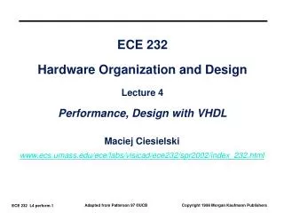
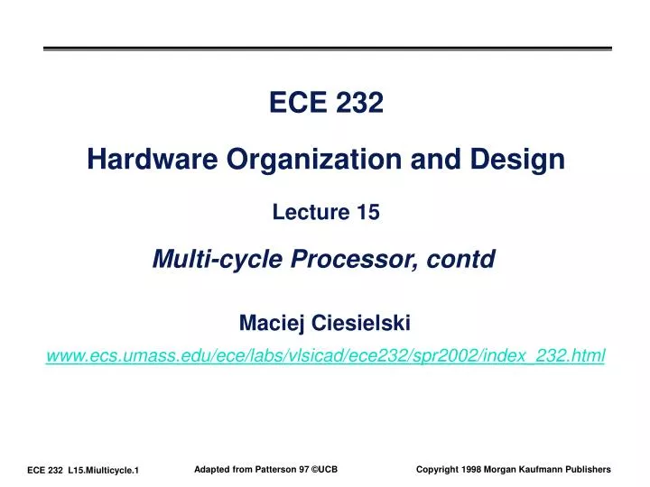
ECE 232 Hardware Organization and Design Lecture 15 Multi-cycle Processor, contd. Maciej Ciesielski www.ecs.umass.edu/ece/labs/vlsicad/ece232/spr2002/index_232.html. Outline. Review of midterm exam I Problematic questions: Overflow detection, MIPS assembly, delay computation

E N D
ECE 232Hardware Organization and DesignLecture 15Multi-cycle Processor, contd Maciej Ciesielski www.ecs.umass.edu/ece/labs/vlsicad/ece232/spr2002/index_232.html
Outline • Review of midterm exam I • Problematic questions: Overflow detection, MIPS assembly, delay computation • FSM-based control, cont’d • Where are we in processor design: physical TR’s • Deriving control logic
Recall: Step-by-step Processor Design Step 1: ISA => Logical Register Transfers Step 2: Components of the Datapath Step 3: RTL + Components => Datapath Step 4: Datapath + Logical RTs => Physical RTs Step 5: Physical RTs => Control
Equal Reg. File Reg File A S Exec PC IR Next PC Inst. Mem B Mem Access M Data Mem Step 4: R-type (add, sub, . . .) inst Logical Register Transfers ADDU R[rd] <– R[rs] + R[rt]; PC <– PC + 4 • Logical Register Transfer • Physical Register Transfers inst Physical Register Transfers IR <– MEM[pc] ADDU A<– R[rs]; B <– R[rt] S <– A + B R[rd] <– S; PC <– PC + 4
Equal Reg. File Reg File A S Exec PC IR Next PC Inst. Mem B Mem Access M Data Mem Step 4: Logical immediate inst Logical Register Transfers ORI R[rt] <– R[rs] OR zx(Im16); PC <– PC + 4 • Logical Register Transfer • Physical Register Transfers inst Physical Register Transfers IR <– MEM[pc] ORI A<– R[rs]; B <– R[rt] S <– A or ZeroExt(Im16) R[rt] <– S; PC <– PC + 4
inst Physical Register Transfers IR <– MEM[pc] LW A<– R[rs]; B <– R[rt] S <– A + SignEx(Im16) M <– MEM[S] R[rd] <– M; PC <– PC + 4 Equal Reg. File Reg File A S Exec PC IR Next PC Inst. Mem B Mem Access M Data Mem Step 4 : Load inst Logical Register Transfers LW R[rt] <– MEM(R[rs] + sx(Im16); PC <– PC + 4 • Logical Register Transfer • Physical Register Transfers
inst Physical Register Transfers IR <– MEM[pc] SW A<– R[rs]; B <– R[rt] S <– A + SignEx(Im16); MEM[S] <– B PC <– PC + 4 Equal Reg. File Reg File A S Exec PC IR Next PC Inst. Mem B Mem Access M Data Mem Step 4 : Store inst Logical Register Transfers SW MEM(R[rs] + sx(Im16) <– R[rt];PC <– PC + 4 • Logical Register Transfer • Physical Register Transfers
A S B M Step 4 : Branch inst Logical Register Transfers BEQ if R[rs] == R[rt] then PC <= PC + sx(Im16) || 00 else PC <= PC + 4 • Logical Register Transfer • Physical Register Transfers inst Physical Register Transfers IR <– MEM[pc] BEQ|Eq PC <– PC + 4 inst Physical Register Transfers IR <– MEM[pc] BEQ|Eq PC <– PC + sx(Im16) || 00 Equal Reg. File Reg File Exec PC IR Next PC Inst. Mem Mem Access Data Mem
PCWr PCWrCond PCSrc BrWr Zero ALUSelA Target IorD MemWr IRWr RegDst RegWr 1 32 Mux 32 PC 0 0 Zero 32 Rs Mux Ra 0 32 RAdr 5 32 Rt Mux Rb busA 1 32 ALU Ideal Memory 32 Instruction Reg Reg File ALU Out 5 32 0 1 4 Rt 0 Rw 32 Mux WrAdr 32 1 32 Rd 32 Din Dout busW busB 32 1 2 32 ALU Control Mux 1 0 3 << 2 Extend Imm 16 32 ALUOp ExtOp MemtoReg ALUSelB Alternative datapath (book): Multiple Cycle Datapath • Miminizes hardware: 1 memory, 1 adder
Our Control Model • State specifies control points for Register Transfer • Transfer occurs upon exiting state (same falling edge) inputs (conditions) Next State Logic State X Register Transfer Control Points Control State Depends on Input Output Logic outputs (control points)
Step 4 => Control Specification for multicycle proc “instruction fetch” IR <= MEM[PC] A <= R[rs] B <= R[rt] “decode / operand fetch” BEQ & ~Equal R-type BEQ & Equal LW SW ORi PC <= PC + SX || 00 Execute PC <= PC + 4 S <= A fun B S <= A or ZX S <= A + SX S <= A + SX Memory M <= MEM[S] MEM[S] <= B PC <= PC + 4 R[rd] <= S PC <= PC + 4 R[rt] <= S PC <= PC + 4 R[rt] <= M PC <= PC + 4 Write-back
next state state op cond control points next State control points 11 Equal 6 State 4 datapath State op Step 5: Datapath + State Diagram => Control • Translate RTs into control points • Assign states • Build the controller Traditional controller Truth Table
Mapping RTs to Control Points IR <= MEM[PC] “instruction fetch” imem_rd, IRen A <= R[rs] B <= R[rt] “decode” Aen, Ben BEQ & ~Equal BEQ & Equal R-type LW SW ORi S <= A fun B PC <= PC + SX || 00 Execute PC <= PC +4 S <= A or ZX S <= A + SX S <= A + SX ALUfun, Sen Memory M <= MEM[S] MEM[S] <= B PC <= PC + 4 R[rd] <= S PC <= PC + 4 RegDst, RegWr, PCen R[rt] <= S PC <= PC + 4 R[rt] <= M PC <= PC + 4 Write-back
Assigning States “instruction fetch” IR <= MEM[PC] 0000 A <= R[rs] B <= R[rt] “decode” 0001 LW BEQ & Equal R-type ORi SW BEQ & ~Equal PC <= PC + SX || 00 Execute PC <= PC + 4 S <= A fun B S <= A or ZX S <= A + SX S <= A + SX 0100 0110 1000 1011 0011 0010 MEM[S] <= B PC <= PC + 4 M <= MEM[S] Memory 1001 1100 R[rd] <= S PC <= PC + 4 R[rt] <= S PC <= PC + 4 R[rt] <= M PC <= PC + 4 Write-back 0101 0111 1010
A <= R[rs] B <= R[rt] 0001 LW BEQ R-type ORi SW Execute S <= A - B S <= A fun B S <= A op ZX S <= A + SX S <= A + SX 0100 0110 1000 1011 0010 Equal ~Equal Memory M <= MEM[S] MEM[S] <= B PC <= PC + SX || 00 1001 1100 0011 R[rd] <= S R[rt] <= S R[rt] <= M 0101 0111 1010 Our final Controller FSM Spec IR <= MEM[PC] PC <= PC + 4 “instruction fetch” 0000 move PC incr here “decode” Write-back
Detailed Control Specification State Op field Eq Next IR PC Ops Exec Mem Write-Back en sel A B Ex Sr ALU S R W M M-R Wr Dst 0000 ?????? ? 0001 1 0001 BEQ 0 0011 1 1 0001 BEQ 1 0010 1 1 0001 R-type x 0100 1 1 0001 orI x 0110 1 1 0001 LW x 1000 1 1 0001 SW x 1011 1 1 0010 xxxxxx x 0000 1 1 0011 xxxxxx x 0000 1 0 0100 xxxxxx x 0101 0 1 fun 1 0101 xxxxxx x 0000 1 0 0 1 1 0110 xxxxxx x 0111 0 0 or 1 0111 xxxxxx x 0000 1 0 0 1 0 1000 xxxxxx x 1001 1 0 add 1 1001 xxxxxx x 1010 1 0 0 1010 xxxxxx x 0000 1 0 1 1 0 1011 xxxxxx x 1100 1 0 add 1 1100 xxxxxx x 0000 1 0 0 1 -all same in Moore machine R: ORi: LW: SW:
Performance Evaluation • What is the average CPI? • state diagram gives CPI for each instruction type • workload gives frequency of each type Type CPIi for type Frequency CPIi x freqIi Arith/Logic 4 40% 1.6 Load 5 30% 1.5 Store 4 10% 0.4 branch 3 20% 0.6 Average CPI: 4.1
Summary • Disadvantages of the Single Cycle Processor • Long cycle time • Cycle time is too long for all instructions except the Load • Multiple Cycle Processor: • Divide the instructions into smaller steps • Execute each step (instead of the entire instruction) in one cycle • Partition datapath into equal size chunks to minimize cycle time • ~10 levels of logic between latches • Follow same 5-step method for designing “real” processor
Summary (cont’d) • Control is specified by Finite State Diagram (FSM) • Specialized state-diagrams easily captured by microsequencer • simple increment & “branch” fields • datapath control fields • Control design reduces to Microprogramming • Control is more complicated with: • complex instruction sets • restricted datapaths (see the book) • Simple Instruction Set and powerful datapath => simple control • could try to reduce hardware (see the book) • rather go for speed => many instructions at once!