Download
1 / 3
30 likes | 184 Views
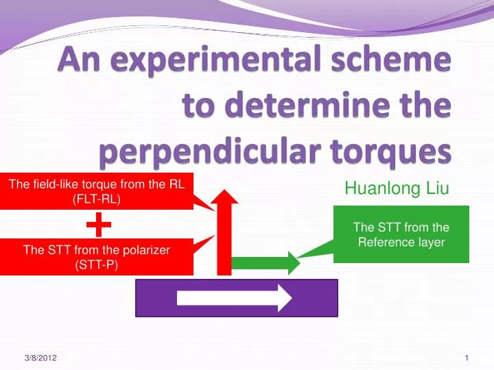
An experimental scheme to determine the perpendicular torques. The field-like torque from the RL (FLT-RL). Huanlong Liu. The STT from the Reference layer. The STT from the polarizer (STT-P). What hysteresis reveals….

E N D
An experimental scheme to determine the perpendicular torques The field-like torque from the RL (FLT-RL) Huanlong Liu The STT from the Reference layer The STT from the polarizer (STT-P)
What hysteresis reveals… • Coercive fields change with voltage, NOT a spin torque effect, because: • STT from the RL should favor one type of switching, switching fields of AP->P and P->AP should both increase or decrease. • Perpendicular torques, namely field-like torque from the RL (FLT-RL) and STT from the polarizer (STT-P), should always help switching, resulting smaller Hc for larger voltage. • Possible explanation: • electric field changes the anisotropy direction at the MgO/CoFeB interface. It becomes more important if (part of) the free layer thickness varies toward the thin end (1.3 ~ 1.6 nm). Experimental reference: Wang et. al, Nature Material 11, 64 (2012). • Revise of our previous understandings: • Under different voltage polarity, the energy barrier for reversal could be different.Therefore, • CANNOT say the strength of STT-P is (much) smaller than that of FLT-RL due to only negative pulse switch.
Experimental scheme • Measurements: • Obtain precessional switching for polarizer pointing up and down (magnetize in strong field), both for, and can only happen under negative voltage according to our previous flip-polarizer measurements. • Obtain the oscillation frequency as a function of voltage. • Analysis: • If the oscillation frequencies under V1 when the polarizer pointing up and under V2 when the polarizer pointing down are the same, it follows: • FLT-RL(V1) + STT-P(V1) = |FLT-RL(V2) – STT-P(V2)| • Since STT-P goes linearly with voltage, we can obtain voltage dependence of the FLT-RL. • Assumption: • Oscillation of real-time voltage signal due to free layer precession (almost) along the normal direction of the plane. • Frequency depends on the effective field and therefore the tilted angle of the free layer. • The tilted angle depends onthe strength of the perpendicular torque: FLT-RL STT-P