Download
1 / 20
200 likes | 291 Views
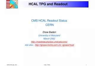
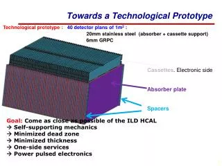
Towards a 1m 3 Glass RPC HCAL prototype with multi-threshold readout. M. Vander Donckt for the CALICE - SDHCAL group. The Glass RPC SDHCAL prototype. 40 1m 2 layers of steel absorber (1,5cm) 6mm thick glass RPCs in 5mm thick steel cassettes Total of 5 λ I

E N D
Towards a 1m3 Glass RPC HCAL prototype with multi-threshold readout M. Vander Donckt for the CALICE - SDHCAL group
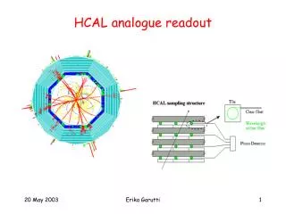
The Glass RPC SDHCAL prototype • 40 1m2 layers of • steel absorber (1,5cm) • 6mm thick glass RPCs in 5mm thick steel cassettes • Total of 5λI • Avalanche mode TFE (94.5% Isobutane (5%), SF6 (0.5%) • Multiple thresholds to allow for the recognition of the dense shower center. • 1 cm2 charge collectors with 3 thresholds • Power-pulsed electronics • Requires no cooling ! IWLC 2010
Cross-section of GRPCs Readout pads (1cm x 1cm) Mylar layer (50μ) PCB interconnect Readout ASIC (Hardroc2, 1.4mm) PCB (1.2mm) PCB support (FR4 or polycarbonate) Gas gap Cathode glass (1.1mm) + resistive coating Mylar (175μ) Ceramic ball spacer (1.2mm) Anode glass (0.7mm) + resistive coating Glass fiber frame (1.2mm) Total thickness including embedded electronics: 5.825mm IWLC 2010
Resistive coating IWLC 2010
GRPC read-out 3 DIFs (Detector InterFace boards) 144 ASICs (HARDROC2 chips) reading 64 1cm2 PADs each IWLC 2010
Cosmic test bench Up to five 8x32 cm Chambers for tracking Trigger scintillator IWLC 2010
Efficiency homgeneity vs HV scan Results obtained using tracking HV scan on 3 different areas. Statguard coated chamber. Top-Right Top-Center Down-Left DIF6 DIF10 DIF9 IWLC 2010
Beam tests • 1 m2 Statguard chamber tested @ CERN-PS in May 2010 – 10 GeV π • 2 1m2 colloidal graphite chambers inserted @SPS H4 (150 GeV π) in September 2010 Beam IWLC 2010
Efficiency homogeneity studies • HV: 7.5 kV • Position scan area • Homogeneous • >95% Results obtained using time selection only 1m2 GRPC map IWLC 2010
Multiplicity homogeneity studies • HV: 7.5 kV • Multiplicity highly depends on threshold level • Homogeneous • <1.3 for threshold ~0.25 MIP Results obtained using time selection only Preliminary 1m2 GRPC map IWLC 2010
Principle of power pulsing Power On Period: 10ms (100 Hz) DutyCycle: 2/10 2 ms Data taking Δt Enable Acquisition Waking time 100 μs Trigger for chip readout Trigger Pulse Generator 2ms/10ms Power On Injecting on falling edge through a 2pC build in capacitor 24 Hardroc2 Scintillator Coincidence & Trigger DIF « In Spill » Signal Enabling Power Pulsing: consumption goes from 2A to 0.7A Veto From Acquisition IWLC 2010 Busy
Power Pulsing Test Beam Beam conditions: 80GeV @ High Rate Aim: PowerPulsing tests using B field. 32x48 cm2 GRPC Beam B field Beam 3T Magnet IWLC 2010
Power Pulsing 3T B field Preliminary 1ms after power-ON : no efficiency loss. Studies are still ongoing to reduce waiting time to 0.1 ms IWLC 2010
Analysis Summary • Efficiency more than 95%. • Multiplicity < 1.3 Pad/MIP (must be re-defined using the 3 thresholds) • Detection rate: Steady up to 100 Hz/PAD • Noise rate: ~0.1 Hz/cm² • Detector working in a 3 Telsa field • Good efficiency/multiplicity homogeneity on large chamber • Validity of power pulsing concept proven. IWLC 2010
Electronics: ASICs test facility The ASICs are ready for the 40 layers. Currently under test, using a robot. Max test time : 10 minutes/ASIC using Labview-based application IWLC 2010
Chamber assembly going on Final total thickness 11 mm aperture 12.5 mm Successful insertion from above IWLC 2010
2x2 X-Y scintillator planes Cosmic rate 200Hz Test bench for production Gas+HV/LV supplies for up to 7 gRPCs that can be tested in few hours Gas mixer IWLC 2010
Mechanics ANSYS simulation of stress and deformation : <150µm Self supporting structure Spaced using bolted spacers Plate assembly under test IWLC 2010
Summary • 1 m2 glass RPCs have good efficiency, multiplicity, power pulsing works. • Not detailed but under control: ageing, gas flow, HV & gas services • 1 m3 construction ongoing to be finished first term 2011 • Ongoing; • threshold calibration using charge injection • Latest Colloidal graphite testbeam result analysis IWLC 2010