Download
1 / 13
160 likes | 377 Views
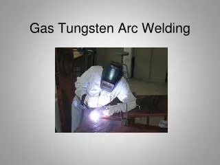
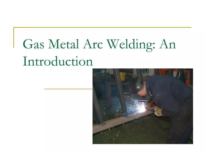
Gas Metal Arc Welding: An Introduction. Gas Metal Arc Welding Defined:.

E N D
Gas Metal Arc Welding Defined: • The Gas Metal Arc Welding Process is a consumablewelding process where an arc is generated between a continuously fed, solid wire electrode and the grounded base metal. Heat from the arc melts the base metal and the wire electrode allowing them to be joined into a solid piece. The molten weld puddle is protected from the atmosphere by an externally supplied shielding gas.
GMAW Equipment Requirements: • Constant voltage or potential power source (DC only). • Wire feed unit. • Welding lead or MIG gun. • Welding cables and ground clamp. • Shielding gas equipment. • Gas supply • Regulator/Flow meter • Gas hose
Advantages of the GMAW Process: • High productivity (most productive of the manual welding processes). • Used to weld ferrous and non-ferrous metals. • Continuously fed wire electrode (fewer stops & starts). • High deposition rates. • Minimal post weld clean-up. • Readily adaptable to automation.
Disadvantages of the GMAW Process: • High initial equipment cost. • Welding equipment is more complex. • Limited portability. • Difficult to use in hard to reach places. • Shielding gas susceptible to drafts. • Lack of fusion with short circuit transfer (cold lapping). • Operator resistance to radiated heat and arc intensity.
GMAW Applications: • Production welding. • Pipeline welding. • Repair welding. • Automotive/Motor sports welding. • Automated applications.
GMAW Variables - Before Welding: • Electrode selection, based on the type of metal being welded. • Shielding gas selection, based on the type of electrode being used and the mode of metal transfer being used. • Voltage setting, based on the electrode size and mode of metal transfer being used. • Short circuit transfer • Globular transfer • Spray arc transfer • Wire feed speed setting (WFS = Amperage).
GMAW Variables – During Welding: • Electrode extension. Electrode extension is the distance from the end of the contactor tube to the end of the electrode. Correct electrode extension is determined by the electrode diameter and type. Correct electrode extension for .035 steel wire is ¼ to ½ inch. Correct electrode extension is critical for maintaining amperage and voltage settings.
GMAW Variables – During Welding,Continued: • Gun angle. The GMAW process can be performed using a leading or trailing gun angle. Up to 20 degrees of gun angle can be used for lead or trailing welding. A trailing or drag angle will impart more heat into the base metal. A lead or push angle will impart less heat into the base metal. Both methods are used extensively.
GMAW Variables – During Welding,Continued: • Travel speed. Finished welds created using the GMAW process should be approximately 10 times the electrode diameter in width. • Electrode motion. Electrode motion mustbe used when using CO2 shielding gas. A half circular, zigzag, back and forth or circular motion can be used. When using argon based shielding gas no gun motion is necessary, but can be used.
Lack of Fusion or Cold Lapping: • One of the major problems associated with the GMAW process is the lack of fusion or cold lapping. Lack of fusion can be caused by incorrect powersource set-up, operator error or both. To help prevent lack of fusion, the welding operator should: • Ensure that enough amperage is being used for the diameter of the chosen electrode. • Prove power source set-up and welding technique by performing a “Clip Test”. • Strive to keep the heat of the arc concentrated on the leading edge of the weld puddle.