Download
1 / 32
330 likes | 514 Views
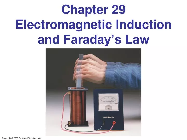
Chapter 29 Electromagnetic Induction and Faraday’s Law. 29-6 Transformers and Transmission of Power. 29-6 Transformers and Transmission of Power. Example 29-12: Cell phone charger.

E N D
29-6 Transformers and Transmission of Power Example 29-12: Cell phone charger. The charger for a cell phone contains a transformer that reduces 120-V ac to 5.0-V ac to charge the 3.7-V battery. (It also contains diodes to change the 5.0-V ac to 5.0-V dc.) Suppose the secondary coil contains 30 turns and the charger supplies 700 mA. Calculate (a) the number of turns in the primary coil, (b) the current in the primary, and (c) the power transformed.
29-6 Transformers and Transmission of Power Transformers work only if the current is changing; this is one reason why electricity is transmitted as ac.
29-6 Transformers and Transmission of Power Example 29-13: Transmission lines. An average of 120 kW of electric power is sent to a small town from a power plant 10 km away. The transmission lines have a total resistance of 0.40 Ω. Calculate the power loss if the power is transmitted at (a) 240 V and (b) 24,000 V.
1 A 120 V 240 V 120 V ConcepTest 29.12b Transformers II 1) 1/4 A 2) 1/2 A 3) 1 A 4) 2 A 5) 5 A Given that the intermediate current is 1 A, what is the current through the lightbulb?
1 A 120 V 240 V 120 V ConcepTest 29.12b Transformers II 1) 1/4 A 2) 1/2 A 3) 1 A 4) 2 A 5) 5 A Given that the intermediate current is 1 A, what is the current through the lightbulb? Power in = Power out 240 V 1 A = 120 V ??? The unknown current is 2 A.
A B 6 V ConcepTest 29.12c Transformers III 1) greater than 6 V 2) 6 V 3) less than 6 V 4) zero A 6 V battery is connected to one side of a transformer. Compared to the voltage drop across coil A, the voltage across coil B is:
A B 6 V ConcepTest 29.12c Transformers III 1) greater than 6 V 2) 6 V 3) less than 6 V 4) zero A 6 V battery is connected to one side of a transformer. Compared to the voltage drop across coil A, the voltage across coil B is: The voltage across B is zero. Only a changing magnetic flux induces an emf. Batteries can provide only dc current.
29-7 A Changing Magnetic Flux Produces an Electric Field A changing magnetic flux induces an electric field; this is a generalization of Faraday’s law. The electric field will exist regardless of whether there are any conductors around: But! But! Isn’t the integral of E around a closed path ZERO? Kirchoff’s Loop Rule?
29-7 A Changing Magnetic Flux Produces an Electric Field Basic requirement of Conservative Potential:
29-7 A Changing Magnetic Flux Produces an Electric Field Example 29-14: E produced by changing B. A magnetic field B between the pole faces of an electromagnet is nearly uniform at any instant over a circular area of radius r0. The current in the windings of the electromagnet is increasing in time so that B changes in time at a constant rate dB/dt at each point. Beyond the circular region (r > r0), we assume B = 0 at all times. Determine the electric field E at any point P a distance r from the center of the circular area due to the changing B.
29-8 Applications of Induction: Sound Systems, Computer Memory, Seismograph, GFCI This microphone works by induction; the vibrating membrane induces an emf in the coil.
29-8 Applications of Induction: Sound Systems, Computer Memory, Seismograph, GFCI Differently magnetized areas on an audio tape or disk induce signals in the read/write heads.
29-8 Applications of Induction: Sound Systems, Computer Memory, Seismograph, GFCI A seismograph has a fixed coil and a magnet hung on a spring (or vice versa), and records the current induced when the Earth shakes.
Summary of Chapter 29 • Magnetic flux: • Changing magnetic flux induces emf: • Induced emf produces current that opposes original flux change.
Summary of Chapter 29 . • Changing magnetic field produces an electric field. • General form of Faraday’s law: • Electric generator changes mechanical energy to electrical energy; electric motor does the opposite.
Summary of Chapter 29 • Transformer changes magnitude of voltage in ac circuit; ratio of currents is inverse of ratio of voltages: and
Chapter 30Inductance, Electromagnetic Oscillations, and AC Circuits
Units of Chapter 30 • Mutual Inductance • Self-Inductance • Energy Stored in a Magnetic Field • LR Circuits • LC Circuits and Electromagnetic Oscillations • LC Circuits with Resistance (LRC Circuits) • AC Circuits with AC Source
Units of Chapter 30 • LRC Series AC Circuit • Resonance in AC Circuits • Impedance Matching • Three-Phase AC
30-1 Mutual Inductance Unit of inductance: the henry, H: 1 H = 1 V·s/A = 1 Ω·s. A transformer is an example of mutual inductance.
30-1 Mutual Inductance Example 30-1: Solenoid and coil. A long thin solenoid of length l and cross-sectional area A contains N1 closely packed turns of wire. Wrapped around it is an insulated coil of N2 turns. Assume all the flux from coil 1 (the solenoid) passes through coil 2, and calculate the mutual inductance.
30-2 Self-Inductance A changing current in a coil will also induce an emf in itself: Here, L is called the self-inductance:
30-2 Self-Inductance Example 30-3: Solenoid inductance. (a) Determine a formula for the self-inductance L of a tightly wrapped and long solenoid containing N turns of wire in its length l and whose cross-sectional area is A. (b) Calculate the value of L if N = 100, l = 5.0 cm, A = 0.30 cm2, and the solenoid is air filled.
30-2 Self-Inductance Conceptual Example 30-4: Direction of emf in inductor. Current passes through a coil from left to right as shown. (a) If the current is increasing with time, in which direction is the induced emf? (b) If the current is decreasing in time, what then is the direction of the induced emf?
30-2 Self-Inductance Example 30-5: Coaxial cable inductance. Determine the inductance per unit length of a coaxial cable whose inner conductor has a radius r1 and the outer conductor has a radius r2. Assume the conductors are thin hollow tubes so there is no magnetic field within the inner conductor, and the magnetic field inside both thin conductors can be ignored. The conductors carry equal currents I in opposite directions.
30-3 Energy Stored in a Magnetic Field Just as we saw that energy can be stored in an electric field: energy can be stored in a magnetic field as well, in an inductor, for example:
30-3 Energy Stored in a Magnetic Field Example: a solenoid