Download
1 / 30
340 likes | 575 Views
Ion Implantation in SiC: 365 MJ Target Spectra. S. Sharafat, M. Andersen, Hu Qiyang, and N. Ghoniem University of California Los Angeles. Glenn Romanoski Oak Ridge National Laboratory.

E N D
Ion Implantation in SiC: 365 MJ Target Spectra S. Sharafat, M. Andersen, Hu Qiyang, and N. Ghoniem University of California Los Angeles Glenn Romanoski Oak Ridge National Laboratory 14th High Average Power Laser Program WorkshopOak Ridge National LaboratoryOak Ridge, TNMarch 21-22, 2006
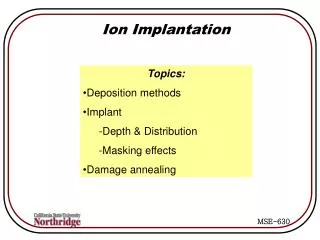
Ion Implantation Issues (9 slides) Possible New Concepts for SiC/SiC (3 slides) Supportive Activities:(2 slides) OUTLINE
Implantation Calculation SiC For each Ion: • Run SRIM at every energy • Add all profiles ( % weighted )
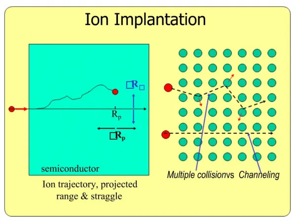
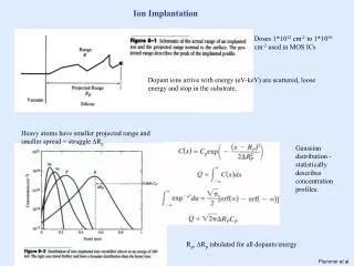
Ion Implantation in SiC Implantation Profile for 1H Implantation Profile for 12C • Sample Implantation Profiles using Perkin’s 365 MJ Target Spectra (SRIM2003) • Profiles for all ions, 1H, 2H, 3H, 3He, 4He, 12C, 13C, Au, Pd were developed Range Range
Ion appm(atomic parts per million) Profile in SiC Per Shot 12C 12C 13C 13C
Ion Damage in SiC per Shot • Ion Damage Profile (SRIM2003) for: 1H, 2H, 3H, 3He, 4He, 12C, 13C, Au, Pd Vacancy Generation Profile for 4He Vacancy Generation Profile for 12C
Carbon Implantation and Formation of WC Carbon Concentration Profile Evolution in W 13th HAPL Meeting
Formation of WC • Carbon reacts with Tungsten to form WC and W2C inside the W-armor • Complex model: (1) Chemical reaction; (2) Diffusion; (3)T-swings; (4) T-gradients. • At 2000 oC solubility of C in Tungsten is of the order of 0.05 at. % • WC forms between 1150 and 1575 K • W2C forms between 1575 and 1660 K Solubility of C in W: D. Gupta, Met.Trans. A 1975 • Need for Experiments on WC: • Effect of H and He implantation on • Mechanical Properties of WC • Helium and Hydrogen Release • Discussions with ORNL(G. Romanoski ) have identified testing facilities (G. Romanoski ) UCLA FusionNETWORK fusionNET.seas.ucla.edu
Carbon Implantation in SiC Implantation of 12C per shot: • Carbon Implantation range: 1.75 mm • For 10.1 m chamber implantation range has ~1x1026 SiC • Number of C per shot: ~6.8x10¹⁹ C/shot: • After 1x10⁶ shots (~1.2 days) C/SiC ratio approaches unity (or SiC2) assuming no diffusion • Concerns Regarding Excess Carbon in SiC: • Carbon diffuses readily (int. + substit./detrapping) • Carbon can bond chemically with H, D, and T • Formation of Hydro-carbons CxHyT retention? [Huanchen, Ghoniem 1994] • Chemical Trapping of H, D, T slows down proton diffusion, defect annealing, and may interact synergistically with He • Pursuing rate of Hydro-Carbon formation
Hydrogen Implantation in SiC Implantation of H, D, T : SEM micrograph image of blisters formed in the 6H-SiC irradiated at 300 K (1.0x10¹⁷ H+/cm2) and then annealed at 1070 K for 20 min. [Jiang, NIMB2000] HAPL:365 MJ Target 10.1 m Chamber ~ 1x10¹⁶ H/m2 Taguchi, JNM2004:Synergistic effectof H, He, +Si implantation: Only He-implantation no bubbles at 1300 oC (Timpl) Dual/Tripple (He, H, Si) Helium bubbles formed at GB • Roughening of SiC (HAPL conditions?) • Effect of Chemical Trapping of H, D, T on roughening? • Experiments: H+-+ He beam (HAPL conditions)?
Nanopillars and Dendrites Ion-Barrier Coating (IBC) Flexible Armor w/o Transpiration Cooling Possible New Concepts for SiC Armor
Possible New Concepts for SiC Armor: Nanopillar { Helium Implantation in CVD SiC:26.3 MeV with 51 degrader foils shows DENUDED ZONE ~0.5 mm near Grain Boundary [Poster by Hu Qyiang] [Chen, Jung, Trinkaus, PRB 2000] • Nanopillars:
Possible New Concepts for SiC Armor: Nanopillars & Dendrites Dendrites “Cauliflower” • Concept is based on: • Make use of characteristic diffusion length of helium (Denuded Zones in SiC ~0.5 um) • Choose materials which have <1 um size features: dendrites, pillars, cauliflower High emissivity CVD dendritic Re coatings applied to solid CVD Re surfaces [Ultramet,2005] Surface textures that were achieved in black W coatings applied to W [Ultramet 2005]
Possible New Concepts for SiC Armor: IBC Coating { The UEET (Ultra Efficient Engine Technology; NASA) is developing SiC/SiC composites with EBC (EBC: Environmental Barrier Coatings) • EBC have low thermal k Melt-Infiltrated SiC/SiC New EBC with no degradation: 300h, 1400oC (2552 F) 1h cycles, 90 H2O-bal O2 Doug Freitag301.570.3821dfreitag@ix.netcom.com4 April 2002 • Ion-Barrier Coating (IBC) SiC Armor: • Glass-forming materials have a relatively open crystal structure, which enhances ion release and self-healing. • Is there a combination of high thermal conductivity materials that could be combined with glass forming materials. (Si3Ni4-MoSi2, Si3N4-SiC, SiOxNyBz ) that will allow for high release of implanted ions ?
Possible New Concepts for SiC Armor: Flexible w/o Transpiration Cooling Use a Flexible Fibers • No matrix material • Fibers should be ~few microns in diameter to enhance Ion-release • Keep armor flexible to accommodate loads Concern: • Thermal conduction path of the weave to underlying structure. Sylramic™ SiC Fiber 2-D Weave • Flexibel SiC-Fiber 2/3-D Weave Armor with Transpiration Cooling: Wetted-Solid Evaporative Cooling • Wick sufficient liquid to serve as a sacrificial layer to take care of all ions • Use structure (W-fibers, dendrites, nanopillars, nano-grains) to hold liquid and to conduct heat
Ion Implantation Issues (9 slides) Possible New Concepts for SiC/SiC (3 slides) Supportive Activities:(2 slides) OUTLINE
FusionNET™ Database: Update • A new category has been added to FusionNET™: • ITER Materials Handbook • All ITER Tungsten Properties are available: · Density· Electrical Resistivity· Emissivity· Enthalpy· Fatigue S-N Curve· Poisson's Ratio· Reduction in Area· Specific Heat· Tensile Strength· Thermal Conductivity· Thermal Expansion· Total Elongation· Uniform Elongation· Vapor Pressure· Yield Strength· Young's Modulus • ITER Li, Be, ClidCop, 316 (LN)IG being uploaded
~1.5 cm Schematic of HiCAT device HiCAT- A Novel In-situ Mass Loss Diagnostic Tool L. Schmitz, P. Calderoni, Y. Tashima, A. Ying (MAE-UCLA) • A compact (~15 mm diam.), high power hollow pulsed cathode discharge has been developed to ionize vaporized/ablated chamber wall material. • Quantitative spectroscopy is used to determine : • Species Composition, and • Density of ablated/vaporized material • High sensitivity, high time resolution detection (< 100 ns) • Operation in Argon background gas (0.01-10 torr) or as vacuum arc • Studied Chamber clearing in Z-Pinch Measured Lithium density compared to vapor pressure equilibrium density (pAr= 0.3 torr) L. Schmitz et al., J Nucl. Mat. 337-339 (2005) 1096
Summary and Conclusions Ion Implantation: “Busy” implantation region (~10-20 mm in SiC; < 5 mm in W) Synergy of implanted H and He (He-trapping, SiC, W) Chemical interaction of excess carbon with H, D, T (SiC, W) WC formation is favored because of low solubility and large negative Gibbs Free Energy of Formation Roughening of SiC due to low energy H implantation Concepts: • Nanopillars/Dendrites: < 1um to enhance ion release from SiC • IBC: Ion-Barrier Coating with glass formers to enhance ion release • Flexible (fiber) w/o Transpiration cooling Supportive Activities: FusionNET™: ITER MPH Tungsten have been added to FusionNET™ Mass Loss Analyzer: In-situ mass-loss analyzer (scan rate >100 ns).
Ocean Optics compact spectrometer Fiber Optic Lens Dual 0.27 m Monochromators PMT PMT Capacitor Bank 2 kJ HiCAT Pulsed High Power Operation Ar Ion Lines Ar Neutral Lines • High density, nearly fully ionized plasma (n < 1017 cm-3, kTe < 2 eV) with local thermodynamic equilibrium (LTE) allows simplified spectroscopic determination of plasma parameters needed to interpret materials spectra. • A Rapid sequence of pulses allows high time resolution (< 100 ns) analysis of mass loss, ablated/vaporized material density, and species composition. • Works in Argon background or as vacuum arc. Z-BoxTest Chamber (Vacuum Capable Glove Box)
HiCAT Diagnostics (Continuous operation) Plasma Parameters obtained from Probe data Schematic showing spectroscopy and Langmuir probe set-up Low current, low plasma density; minimally invasive diagnostics; highest trace detection sensitivity under equilibrium conditions. Required back-ground pressure 0.01-10 torr Argon Emission Spectrum End-on View of HC Discharge in Argon Ar neutral lines Ar Ion lines
Density Profiles (SRIM) DEBRIS-IONS 12th HAPL Meeting
Impact of Carbon Implantation: Tritium Retention • High T implantation: ~2x10¹⁷ T/m2 per shot for a R=10.1 m chamber. • Effects of Carbon on T retention at High Temperatures? Irradiated tungsten at 653K with carbon concentration as a parameter (1 keV ~7× 1024 H/m2[Ueda,2004].